Search the Community
Showing results for tags 'plus2'.
Found 13 results
-
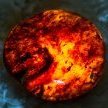
I've just tried to install the chip using this guide: https://consolemods.org/wiki/Xbox:Aladdin More precisely I soldered the pin header and the 3.3V, LAD0, LAD1, LAD2 and LAD3. I made a blunder and ruined the trace by R7P4, so needed to reroute it. I would have routed through the hole at the chip pin, but the hole had solder in it that I haven't been able to remove, so I resorted to the hideous mess you can see on the picture. I have checked all the connections with a multimeter. There is 3.3 on pin9. LAD1-3) I have checked as much as I could by putting one of the multimeter probes on the tip of the pin and the other on a point on the trace that is not the solder point directly. In other words, I am reasonably sure that the soldering is "ok" I also cut the L trace because the MrMario2011 video said so. But when I booted only a black screen would show and FRAG. So I restored the L trace to be able to boot into stock BIOS. Now I can only boot into stock. Am I missing something? Have I done something wrong? What can I check? The chip lights red whenever power is plugged into the xbox. I noticed that if I put the chip in with the BT not soldered on the chip the led would dim slightly whenever the xbox was turned on. After I soldering it, it would not dim. Don't know if it means anything. Just mentioning it.
-
 Hi, have a Xbox Classic 1.4 chip FOCUS fitted with Aladdin XT Plus2 Cerbios 2.4.2 FRAG when power on Falshing Green Orange NO video output on screen. I replaced 3 capacitors of 3300uF 6.3v the ones near the power connector were swollen, and put new thermal paste, and washing mainboard. How to fix?
 -
Hi all I have a 1.6 xbox fitted with an Aladdin XT Plus2 which has the correct chip fitted not rebranded clone I want to flash it with cerbios but I'm not experienced with this at all and don't want to get it wrong I have a 2tb sata drive partitioned with fatxplorer ready to go Could someone help me or point me to an accurate guide, all the ones I've checked all seem to do it a different way lol Thanks in advance
-
I'm trying to write a bitstream to a spare Aladdin XT2 Plus modchip with a knock-off USB Blaster. The USB Blaster in question is one that came with an AliExpress FPGA dev board. It looks like an official product, literally says "USB Blaster" and "Altera" on the sticker. One of those knock-offs. I only mention this because it could pertain to the issue. The github page linked says to externally power the modchip, which I am doing. I've found that if I connect 3.3v from an Adafruit trinket and leave the 3.3v line from the USB Blaster connected, I am able to run `urjtag` on Linux, connect the USB Blaster, and run the `detect` command. This reads out the device ID and hangs. I give the process a `SIGINT` and it segfaults. Seems promising, but I don't trust this to write the configuration to the chip. Possibly an issue with `urjtag`, but I can always debug that myself. Should the USB blaster be providing 3.3v while there is an external source providing 3.3v? This doesn't make sense to me, but it's the only way I've been able to get a partially successful ID from the Lattice chip. I also have this power supply. It takes my 12v wall wart and gives me some nice 3.3v headers. I've double checked with a multimeter and it seems to do what it says. When I power with this, it does bad things to the USB Blaster. I tried first without the 3.3v line from the USB Blaster and again with the 3.3v line connected. Both times, the USB Blaster is not even detected by my computer. It takes a minute or two of being unplugged before the USB Blaster is recognized by my computer again. This particular power supply has an on/off switch. I can switch it to off, plug in power leads to the modchip, and this still messes up the USB Blaster. It won't be detected even though the external power source is turned off. What could be causing this? Completely out of scope, I've heard that the Xecuter 3 uses a Lattice chip in the same LC4XXX family. From what I understand, they scrubbed the markings on the CPLD and made it look like an Actel chip to make cloning more difficult. There's a schematic publicly available, but from what I can tell, it requires transplanting chips from a working Xecuter 3. I seem to recall hearing that they locked the chips during manufacturing so the configuration / bitstream couldn't be copied. Does anyone have any recollection of this?
-
Hi there, I'm back doing another 1.6 mod with an Aladdin XT Plus2. It's a stock 1.6 xbox, so I thought a modchip would be pretty straightforward... Added the pin header and the tutorial I followed said cut the pins marked with an X (hopefully this makes sense) X O O O O O O O X X O O I've rebuilt the LPC and cut the L Frame trace, linked the BT to enable chip at all times, soldering went smoothly, no traces pulled etc. This is my third xbox mod install hi When trying to turn it on, I get the 3 restarts and the green red flashing ring led Any help or checklists to work through would be hugely appreciated, I can add photos tomorrow Cheers, Bryce
-
I have like 6 1.6 boards that I was going through and was pre-emptively rebuilding for OpenXenium chips last year. Fast Froward to this year and OpenXenium doubled in price and are usually sold out anyway. Decided that I'll just grab some of those cheap Aladdin XT Plus2 knock offs from aliExpress and buy one of those re-programmers for the chip. I have only installed OpenXeniums so this is my first experience with these Aladdin Chips. Was looking this guide here on the forums and instead of wiring the D0 to a point on the pin header like with OpenXenium it says to ground it to something on the board while the comments say to ground it to the D0 point on the chip. Just wondering what would be the best practice for these chips. Also in the steps it does not mention cutting the trace on the L-Frame which I always heard was a must with these Aladdin chips.
-
Hi all, I've been out of the scene for ages, but recently saved a few xboxen from clock cap death and bought some aladdin chips to mod them with. Also got some SATA to PATA converters, which I haven't gotten working: proper 2 cap version with the master / slave jumper and an 80-pin cable, seems to cause a conflict with the DVD drive in every config I can think of - OGXBOX DVD shows "linux" and then DVD keep seeking back and forth forever. I thought I'd update the bios to see if that helped. I've gone through as many threads related to this topic as I can e.g. https://www.ogxbox.com/forums/index.php?/topic/3866-aladdin-flash-not-writable/ and tried the suggested solutions, but I am unable to flash a new bios to my modchip. I' going to try and provide as much information as possible as well as the things I've tried, in the hope that someone can assist. Top side of the board (this is one I haven't installed, installed one is identical with BT and D0 connected correctly, chip boots fine): Bottom side of the board: Stuck on erasing (and bios ID): Bios hashes: I'm using OGXBOX Installer 2021 DVD. Xbox is reported as 1.4. So I've tried the following: xflash for sst49fl020: seems to be able to dump the flash, but fails on flash with an "Flash check id failed, are you sure you have flash enabled?" XBlast 0.56: select evoxm8_67. when I press both triggers, start and white, the xbox reboots (wtf?) OGXBOX menu flash: gets stuck on erase as per the image above Tried the short and long power button presses, doesn't seem to change anything. "Chip: Protected" appears on the OGXBOX screen Any suggestions? I do have a minipro programmer somewhere with (I think) the correct adapter so could try that as last resort. Thanks -j
-
hello guys, i'm new and i'm really desperate to find a scheme for an xbox with 1.0 board...i only find scheme or videos for 1.6 ... i'm stuck i'm following this tutorial but ofc the board is different and i dunno which cable go where https://www.youtube.com/watch?v=RNZOVTKGeDk
-
tried to install the aladdin xt plus2 on my 1.6 and ... last connection i had to make didnt go well ... i feel bad the point didnt want to tin, ended up destroying the point and traces around it is there anyway can i fix this mess ? https://ibb.co/FY4vbT0 https://ibb.co/nRq48GJ (its my first time soldering dont be too mean on me lol) thanks for future inputs
-
Not done a chip install before but decided to take the plunge and have just received an Aladdin XT PLUS2 including pin-header. Thing is I have two options: install on a v1.0 or a v1.6. I've started by bridging the BT to adjacent GND point so when fitted the chip will be always be on. A bit fiddly and I overcooked the solder on one end but it looks clean enough. The question is what to do now: there are plenty of guides for the the v1.6 but that involves rebuilding the LPC which with my soldering skills I'm not 100% confident about. There is also contradictory information about the pin-header set up too. Some guides remove just one pin others like this very clear YT guide recommends removing four pins. The v1.6 LPC hassle made me tend towards using the v1.0 instead but the guides I've found for that are limited and seem unclear in comparison. Nothing at all about using the pin header, if there are any differences, and the pins that need removing or even what needs to be connected to what. Available pictures are particular poor. It also appears that to use the pin header I'm going to have to remove the existing solder from the LPC holes too. Is the info in the v1.6 YT tutorial about using 5v from the right transistor leg to make the LED only switch on when the Xbox is powered up applicable to the v1.0? Advice/info please.
-
How are y’all doing? I’m trying to install the Aladdin chip on my 1.4 motherboard and I need to know if I need to solder the LAN and the HD to the Aladdin chip?
-
I was able to softmod 1 of my 2 Xboxes using a purchased game save, with the necessary files. I ordered an aladin plus 2 chip and will attempt to install to my other. Is there a process I need to do to clean the motherboard prior soldering? Thanks
-
Hi, so I've used this guide to install an Aladdin XT PLUS2 into my rev 1.4 Xbox. I soldered D0 to the chip and bridged BT so the chip is always on, but as soon as I power up the system, the screen stays black. If I unplug the chip it normally boots. At first I followed the guide and soldered D0 to the LAN LED's ground, but then the Xbox would just boot normally without the EvoX logo, after I soldered D0 to the chip, the black screen problem appeared. (FYI I took the pictures when I still had D0 soldered to the LAN LED's ground. Oh and Ignore the 4 pins at the top, I was too fast and placed the pin header wrong, so I had to solder on 3 other pins) I already checked the solder points three times and tried to reflow the solder points two times in hopes that I just messed up soldering the pins, but that didn't help either. Can somebody tell me what the cause for this to happen could be? The system doesn't FRAG, HDD spins up, but the TV just stays black.


Board Life Status
Board startup date: April 23, 2017 12:45:48