
Bowlsnapper
-
Posts
4,208 -
Joined
-
Last visited
-
Days Won
109
Content Type
Profiles
Forums
Calendar
Store
Everything posted by Bowlsnapper
-
Updated to 1.3.0 Changelog in the description.
-
Sorry, no ini. I was mixed up. With EVTool, you couldn't enable IGR to work?
-
It may have been a non-standard button combo. Or more likely, or hard-coded off with EVtools when patching.
-
@tiertop Expanding upon Marty's post here, it may be possible that there is a short or something fishy about grounding that is causing attenuation/dimming in the LED or blocking the data signal from reaching the transmitter entirely. Definitely look at ALL the wiring in there.
-

Can I solder a USB cable directly to an Xbox controller board?
Bowlsnapper replied to tktagmedia's topic in Hardware Mods
There is not currently an "open-source" or alternative solution to this adapter (communicator). Although with all the Halo 2-ness that is happening, a solution is being explored by multiple people. I know that alternative sources for the existing supported chipset are being explored as well as possibly other solutions. A generic audio adapter will not work, as far as I am aware. -
Not much to replace there... There's a ceramic capacitor, but I think those rarely go bad... Maybe try replacing both that and the SPDIF LED module?
-
You seem like you are an experienced guy... I'm sure you tried another chip just in case that one is DOA?
-
It does? I haven't had any on all the consoles I've run it on... What issues are you experiencing?
-
Wanted to add that bridges are easy to avoid if you use a shit ton of flux (obviously) and then only add a little to the tip of your iron and do the drag method. You can always add more once you sap all the solder off the tip of your iron, but if you have too much, you'll end up with bridges and needing to remove it. Although I don't wick right away, I'll try to go along another side/row of pins and move some of the solder from one row to the next that I work on. Much easier... and you'll need less solder for that next row you started. And never get solder into the vias around the chips. I have no idea why, but it kills motherboards. If it happens, use braid to get it out of the via before you run power through the board... seriously.
-
Wanted: Console with 128mb ram & MakeMhzHDMI mod
Bowlsnapper replied to JackedLynx's topic in Wanted
I cannot possibly express the condolences that would be appropriate for the level of loss here. If something like that happened to me I would slit my wrists. I mean... are you sure EVERYTHING is toast? Could some of it not be disassembled, cleaned, ultrasonically cleaned, and saved? As long as power was not going through these things it's possible that water didn't destroy all of it once dried. Why was all this in the basement and why did it flood so catastrophically? -
Wanted: Console with 128mb ram & MakeMhzHDMI mod
Bowlsnapper replied to JackedLynx's topic in Wanted
... That's pretty lackadaisical considering what it is you just said. Dude I am so SORRY. That would be a point of mourning in my life for fucking decades. I have one in a Halo edition. Not sure I am willing to sell since I'm a bit attached to it, but who knows, I'll think on it. What all was lost? -
What do you actually need them for, at this point?
-
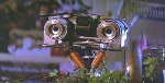
Debugger wired up with relocated TX & RX LEDs Quite the shitstorm of wires, I know. But as long as they're never seen... fuck it. I'll hide the wires better Here it is. SuperIO RX and TX lights working on the left. On the right side, from left to right: DVD activity, DVD Ready, HDD activity, LAN activity. This was a long project, but worth the work. I wanted to do a Development kit, but with a little more than the LAN debugging that came with the regular Debug kit. This more like a mix between the DVT-2 (Debug Kit) and DVT-4 (Development kit). The DVT-4 had serial debugging at the kernel level, as opposed to just LAN (XBDM). I wanted to internalize the serial debugger, so I did, keeping things neat. The only thing is, I would not have view of the Transmission/Receiving LEDs if I did so, so I soldered molexes to the SMD LED pads on the debugger and relocated the LEDs up front. At first I had issues with the debugger, but I managed to finally find some loose pins on the SMSC chip on the debugger linking the chip to the LPC. Once that was fixed, I had to swap out the 1.4 board I was planning to use with a 1.0, since I determined that Lframe could not be made to work on the 1.4. I basically trashed the via on the edge of the MCPX and couldn't repair it. JESUS that thing is fragile. So I plugged it into the 1.0 and I got output through Windbg. Awesome. Then I saw the video of the status LED array and wanted to do the same thing, so I did. A very statusy and verbose console I have here. I call it the DVT-5. Lol. Obviously the console is upgraded to 128MB of RAM. The SuperIO debugger case is printed green (off color but still) as well as the fan shroud. Also printed some green feet since 3 were missing and the one remaining was falling off. The clips used for the LEDs are 3D printed as well. I went with PETG instead of resin, since I have shit luck with resin and everything I make with it turns into crap. lol. The software setup is TSOP flashed Cerbios 2.3.2 Hybrid flagged as debug in the ini. I wanted to keep the LPC free for the SuperIO ribbon. You can do an LPC breakout and have both the debugger and a modchip, but it served no purpose for me and I wanted as much space as possible. I have a PBL out to retail (XBMC) and will create a shortcut in the future so that I can load XBMC straight from the XDK if I need to debug through it for whatever reason. The HDD structure is just like my other HDDs and consoles. 2TB with XBMC as the main and based on the Origins image. The debug flag in the ini is what gets me to boot into the XDK dash. However, I still need to learn to code, so I will probably start with hello world, and then write my first app installing and then enabling or disabling the FPS overlay DXT extension. The USB-C breakout I used is here: https://www.adafruit.com/product/4090 This is what fits into the Rear USB-C breakout board mount STL I included in the bundle. Buy one, it's only a few bucks, but get the 1 Ft cable, too. Forgive me for not doing a pinout, but a pinout can be done yourself with a multimeter and a cable with the wires exposed on one end and the other plugged into the jack. That's what I did. You have to put the cable through the RF shield and then solder the wires to the board... unless you wanna just cut some of the grille off the RF shield. However, you do need to fit it into one of the bottom vents (the bottom left, looking at it from the inside of the case) and you will see a channel in the bottom of the fan shroud for the USB cable to go through. Line it up with that. I have included in this package all the 3D prints, wiring diagrams and info (Gerber, BOM) for the SuperIO debugger that I used to make this development kit. If you need anything, ask me. Debug Kit Goodie Bundle: https://mega.nz/file/JqdiFTqb#Ca4eF9tDnwTdIUDDyewTpFyj7p-Jqa73LLHCZmvV5jU
-
I found it. Lan and HDD activity LEDs have cathodes to the solder points, with resistors. DVD activity are anode to points. I need to take a closer look and see why this is not working. I suspect a short. I will try to ask him for gerbers of the PCB and parts, but I think that this is his baby.
-
Wow... I remember the days when you could send a console in the be repaired... is that still a thing, or are consoles disposable now?
-
The HDD and LAN activity LEDs have the cathode go to the point indicated. DVD points, however, must have anodes go to the point.
-
Haven't come across that yet. I would completely disregard a "refurbished" sticker. May mean something to the average person but not to us.
-
Well, It's basically done. I didn't get the DVD "Ready" light to work (it kept fucking with my DVD ROM drive and making it act funny), but I did get the activity light going, separate from the HDD activity LED. LAN is there as well. The two on the left are the RX and TX LEDs for the Super IO debugger. I'll test more tomorrow with the XDK and debugging through LAN, but it looks like this project is good
-
The relocated debugger RX and TX LEDs are working.
-
I got the debugger working. First, some pins were loose on the SMSC chip linking to the LPC pins. Now, it will not work with the 1.4 board I'm trying to use, because the LFrame via is borked. I already know, man. I gouged the shit out of it. Anyway, if I have to use the 1.0 that I used here to test the unit, then I will, but I'm gonna try to get the 1.4 Lframe working. Project is back on track and the BOM I posted is good.
-
Ah, okay. So if all that has happened, then I would reapply a thermal coupling solution.
-
It will be made easier to go into a modded dash with a retail BFM bios from the XDK dashboard and just launch games from XBMC, UnleashX, etc.. In order to launch retail games from the XDK dash, it's kind of a pain (it can be done a certain way) and honestly would not really serve a purpose.
-
If your temperatures are normal, then thermal paste is not necessary and it will not fix this. Also, if the graphical errors are present immediately upon boot, then the artifacting is not being caused by overheating. Really, in the case of the Original Xbox, the thermal glue that is used is pretty much fuckin' bulletproof. That stuff is incredibly durable. In fact, if your temperatures are good, I would not remove the stock cooling compound setup. It just would serve no purpose. If you have never removed those sinks and they have never been apart from the motherboard, I would assume that your thermal compound is intact and is still doing the job it was doing 20 years ago.
-
Yes you can... However, you will be limited to UDMA 2 speeds, reliably. You can either flash the UDMA 2 version of Cerbios for the time being, or flash UDMA 6 to get prepared for the cable and just boot into safe mode using the eject button to power on. Using UDMA 6 will definitely result in an error.
-
Very briefly, could you just tell me where to put it and anything else that may be necessary first? I use XBMC4XBOX. I'm just not familiar with addons. Sad, because the profiles I'm seeing in this thread are no longer active after 5 years. lol.


Board Life Status
Board startup date: April 23, 2017 12:45:48