

KaosEngineer
-
Posts
4,874 -
Joined
-
Last visited
-
Days Won
459
Content Type
Profiles
Forums
Calendar
Store
Posts posted by KaosEngineer
-
-
5 hours ago, Bowlsnapper said:
Kaos, when it comes to these chips OS firmwares, what exactly makes them unable to run? As far as I know the Xenium (for example) does not have an eeprom like the X3 did, so why will they not boot and run just like they would on any other 256k bank?
Most of those OS firmwares look for specific ID values being present in the hardware devices on the modchip. If they don't match, they will NOT work. Or, FPGA/CPLD code which defines/creates internal registers used by the firmware are not present for the OS to run.
-
 1
1
-
-
6 hours ago, Gigamaximus80 said:
If you have a schematic or troubleshooting guide for the Tuscany power supply that would be greatly appreciated.
I've never found a schematic/manual for any Xbox Power Supply Unit.
-
It has 2 512KB sized banks. You can flash any 256KB or 512KB modified Xbox BIOS to it.
PrometheOS, SmartXXOS, XeniumOS, etc. are modchip control firmware which won't work.
The latest BIOS is CerBIOS. It is a 256KB modifed Xbox BIOS.
Edit: Which modified Xbox BIOS to flash to the modchip depends on which Xbox version you have. Not all modified Xbox BIOSes work on v1.6 consoles.
-
 1
1
-
1
-
-
9 hours ago, dmuney said:
Unfortunately no, I don’t have any of the parts related to power control
Purchase a wired 2-pin connector and ground both wires to activate the backup BIOS.
You could use a couple of lengths of 26 to 30 AWG wire-wrap wire soldered to the back of the pins on the modchip to make the connection to ground.
-
On 2/24/2024 at 4:26 PM, dmuney said:
My issue is that my chip does not have the power control board installed, so I cannot use the power+eject button trick to get to the bios recovery screen.
Do you have the double red wire cable that connects from the modchip to the power+eject board?
-
The bottom PCB is what is needed to have the switchboard. There is no replacement for the plastic sticker that was placed on top of the original PCB with all of the labeling on it. Maybe you can have one custom made.
The developer of the replacement chunky unit made it out of three thin stacked PCBs. Only one, the bottom PCB, has electronic components installed on it.
-
1
-
-
4 minutes ago, KaosEngineer said:
I have not done anything with my original Xbox 1.6b since I softmodded it over 15 years ago, and recently it stopped powering on.
I've tried googling and researching, but the loss of Sickmods (and others that I probably don't know about) has made it difficult to find information.
Measure the voltage level present on the standby 5Vdc lines when AC power is connected. Does it have 5Volts present?
-
On 2/20/2024 at 1:04 PM, Gigamaximus80 said:
Hello everyone.
I have not done anything with my original Xbox 1.6b since I softmodded it over 15 years ago, and recently it stopped powering on.
I've tried googling and researching, but the loss of Sickmods (and others that I probably don't know about) has made it difficult to find information.
Attempts So far:
- Eject or power button does nothing.
- Replaced the 5 main caps that are known to leak (I'm pretty sure I did this 10 years ago as well, but had parts on hand so did it anyways)
- I have replaced the transistor near the clock cap (q7c2)
I'm pretty sure its the power supply itself, (Its the Samsung Tuscany one) so I have been trying to modify an ATX supply to use to test.
On the earlier versions of the XBox there are lots of information and adaptors, but not the 1.6b.
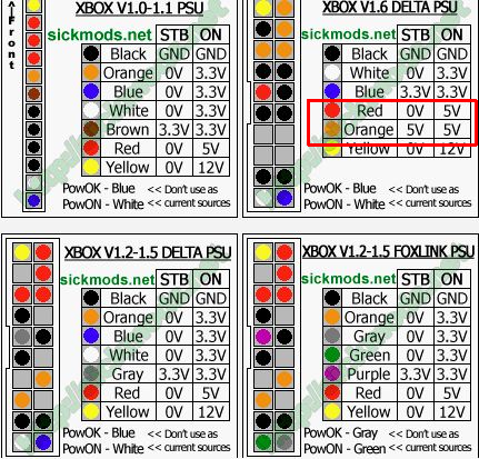
The pinouts I have found for the 1.6 xbox (See below) show it needing 4 lines on 5Vsb, and only one standard 5V line:

I'm pretty sure this is backwards, and it should be 1 standby line and 4 regular, can someone with more experience confirm?
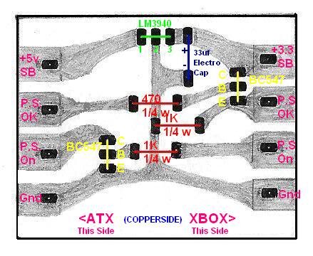
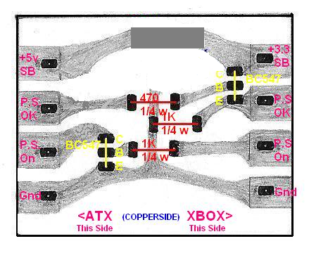
The other question is regarding the N64Freak adaptor board diagram:
From what I have read the 1.6 uses 5Vsb instead of 3.3Vsb, can I omit the LM3490, the 33uf cap, and the link to the ground plane like so:
Thank you in advance for any help you are able to provide, and if you have any good tips for a guy who is 15 years out of the scene, let me know.
")
The ATX to Xbox adapter above is only for v1.0-1.4 Xboxes, not v1.6s. (See: SICKmods : ATX PSU Converter > About (archive.org))
IIRC, sickmods.net never released a v1.6 compatible ATX to Xbox adapter - they did release an updated version 2 different than what is pictured above. However, it too is only for v1.0-1.4 Xboxes, not v1.6/1.6bs. (See: SICKmods : ATX PSU Converter 2 > Install It (archive.org))
Which Xbox version depends on the cable/connector you install on the Xbox side of the PCB. A 1x12 connector and cabling for v1.0/1.1 or a 2x10 connector and wiring for v1.2-1.4.
-
Download the xbmc.log and xbmc.log.old (or is it xbmc.old.log) files. Open them in a text editor to check for other error messages.
Debugging will most likely need to be enabled then try installing the addon again to log more info to get a better understanding of what is causing the error.
-
If not already, check out the Steel Battalion Online subReddit:
and Discord server for online multiplayer gaming:
IIRC, they use XLink Kai to play with others on the Internet:
-
1
-
1
-
-
2 hours ago, peterpop said:
The clock capacitor luckily looks in pretty good condition. No leakage.
Many people say this; however, the cap has leaked all over the motherboard.
Please post/share a picture of the motherboard and/or area around the clock cap.
-
1
-
-
8 hours ago, Kattmandu said:
Test with the console plugged in or unplugged?
Plugged in. Be careful not to touch any exposed metal parts on the PSU.
-
1 hour ago, PRince404 said:
Is it only intended for Xenium? I thought it would work on every modchip.
PrometheOS is a replacement OS for the Xenium modchip. It is not a modified Xbox BIOS that runs games/homebrew apps. It is software to control the modchip and do maintenance operations on the console.
-
23 minutes ago, arfows said:
follow on question is that I don't have 3300uf caps but I do have some 2200uf.
Are the 6.3Vdc, low-ESR, 105 degree Celcius rated electrolytic caps?
-
On 2/6/2024 at 8:09 PM, Slickaroo2 said:
Clean that PCB. Edit1: Oh wait, it used to have a double-sided foam pad on it to hold it in place inside the console. Didn't it?
I don't think the solder bridge between the 3rd and 4th pins on the bottom
right-left-hand side of that PCB is to be there.Edit2: Reworded content. My other right - the left-hand side of the first picture.
-
1
-
-
22 hours ago, arfows said:
So I buggered up the soldering of R7D1 to R7D2 and lost the transistor or whatever it is that normally sits on R7D2. What affect will that have?
There is no soldering of R7D1 to R7D2. The R at the front of the part's location designator stands for Resistor. R7D2 is a resistor. A pull-up resistor if I remember correctly. I believe it has a value of 10 Kilohms but I'll need to double check its value before you take that value as fact. I do believe it is needed for proper operation of the console. Edit: Found a post on reddit.com that says it is a 10 KOhm resistor. SMD resistor physical size: 0402.
You need to add a solder bridge or some type of electrical connection between the two pads at location R7D3 on a v1.0/1.1 Xbox motherboard.
The two pads where R7D1 is located are bridged on v1.2-1.4 motherboards and R7D10.
See: TSOP Flashing Unlock points (biline.ca)
Which version of motherboard do you have?
QuoteOn another note, I opened a stock box to check on Caps. While I have the motherboard out, can I go ahead and solder the two points before ive done the softmod portion?
Thanks
Yes.
-
7 hours ago, Bowlsnapper said:
Sorry to be a bother, but are you able to explain why these failing components would result in higher current draw? Is something behind them pulling more current as a result? I am in electronics classes and I feel the answer may be interesting if you have the answer.
@HyPeRcOoLeR +1 for the CRT.
If the resistors or a capacitor shorts, more current will be drawn. Caps; however, I believe will open instead of short when they go bad.
-
1
-
-
1 hour ago, HyPeRcOoLeR said:
Do you know where those capacitors located?
Thank you for your help btw

On the controller card inside the DVD drive and on the hard drive.
-
Just now, KaosEngineer said:
I Guess the RED-Black is too low, but interesting that it works after i replug the IDE Cable.
This tells me that there's something pulling too much current on the IDE bus until after the hard drive has finished spinning up.
There are most likely bad caps and or resistors on either the hard or DVD drive's controller boards.
-
2
-
-
17 minutes ago, HyPeRcOoLeR said:
I bought this box with the modchip pre installed. The HDD Is a IDE 250GB Samsung SP2514N (I tried with other IDE Drives and same problem after while)
IDE Cable is fully seated in. The DVD Drive works fine. Measurements: Yellow-Black 11.1v RED-Black 4.7v. I Guess the RED-Black is too low, but interesting that it works after i replug the IDE Cable.
Thank you guys for the help.
Voltages for the hard drive usually have a +/- 5% or 10% tolerance.
5Vdc range: 5 + 0.25 = 5.25 Vdc maximum to 5 - 0.25V = 4.75 Vdc minimum
12Vdc range 12 + 0.6V = 12.6 Vdc maximum to 12 - 0.6V = 11.4Vdc minimum
To me, both required voltages for operation of a 3.5" hard drive are a bit too low.
You'd need to check the specs of the specific hard drive to see what the hard drive's power supply tolerances are.
-
1 minute ago, Fringle said:
I was going to suggest that was it's location but since I'm at work and don't have a board here to verify it actually went there I didn't want to misleading. The second board he posted also don't have a cap in that spot so I'm not convinced that's where it came from unless both boards have the same missing components.
I'll need to see if I have any v1.0 motherboards lying around to check if that same cap is missing on it or not.
Not sure I'll get to it tonight.
-
2
-
-
3 hours ago, Fringle said:
Since you have a modchip, the tsop being damaged is probably not the issue. I'd be more concerned about the smd capacitor that is sitting on top of the other one in the first picture. You'll have to figure out where that came from and solder it back in.
Looks like C7D4 is missing. That piggyback rider probably goes there.
And those two small resistors need to be put back where they go.
Any other loose SMD components on the motherboard?
ST M29F080T-90 Flash memory chip.
The sticker on top covered all the manufacturer's labeling.
ST M29F080A-90, Hyundai or Hynix HY29F080T-90 flash memory chips will work to replace the TSOP.
-
1
-
-
On 1/28/2024 at 1:29 PM, Peppie said:
It did not say where it was installed. ut as I said will open a topic el
My old version of XBMC4Gamers was not completely installed and showed me the path. Upon installing the latest version, it did not show me the path that the old version did.

I suggest running UnleashX. Move down the list of games to the one you are interested in finding where it is stored on the hard drive. Press the Start button to open the context sensitive menu. Move down to the Information... menu item then press (A). The path for the game will be displayed.
Quoteswhere in this forum
New Topic in
Software > Games
or
Software > Dashboards.
-
1
-
-
7 hours ago, Peppie said:
I have a 1.6 with smartxx chip and flashed it with cerbios. Great bios for the fact I can run cci format games.
I might haveto open another topic for this but I wanted to copy a game frokm my harddrive to my new xbox with the xecuterchip.
I have the whole cci library on my pc and installened on my 2TB drive in the 1.6 Xbox. But....... I can not find the folder for the chronicles of Riddick escape from butcher bay......
I have searched it on the HDD from teh PC also on the HD from the xbox with filezilla but it is not there. The game shows up in xbmc4gamers but not in the filemanager....
very strange. I noticed when I only enable the foldername in the game view of xbmc4gamers it does not have a name. when I enable game name or both (game and folder) the name is shown under the image of the game.
I want to copy the game but cannot find it.... very odd!!! Maybe it is in a different folder name?
Press Y for Synopsis View and go to the Info screen. It may show you the path where the game is installed. I know it did on my older release of XBMC4Gamers; however, I did not have the artwork or synopsis info downloaded to my console.
I'm installing the latest version, updated within this last week with updates even a day of two ago, to see if the same thing happens with it.
Board Life Status
Board startup date: April 23, 2017 12:45:48
Xecutor 2.2
in Hardware Mods
Posted
Archived X2.x Pro DIP Switch Settings:
http://web.archive.org/web/20141025141741/http://www.xbox-scene.com/modchips/x-ecuter2_pro_switches.html