

KaosEngineer
-
Posts
5,063 -
Joined
-
Last visited
-
Days Won
479
Posts posted by KaosEngineer
-
-
On 3/18/2025 at 2:37 AM, smkirnats said:
i dont know how to check the dasboard boot order, but it looks like the problem is the startup of dash, if i launch installed dasboard via file explorer it works.
Can you post a close-up picture of the modchip, please?
-
On 3/18/2025 at 2:27 PM, smkirnats said:
BIOS checker says this:
KaosEngineer here, I removed the picture to save space
Run Evoxdash's Flash BIOS option. What are the manufacturer and product IDs it displays when you try it. Don't continue after it displays these values:
HOMEBREW (ffff) shown by BIOSChecker isn't what I expected.
I'll check to see if the BIOS MD5 hash value, 2FDD6851B32AE931637D4845C037B550 - I think that's the value in the image, a bit blurry to me - is in the evox.ini files I have.
Edit: Found that value but another not what I expect to see for a BIOS's MD5 hash:
(1MB)BLANK (do not flash it!)=2FDD6851B32AE931637D4845C037B550 (I've not seen this BIOS version ID before now!) More research needed.
Is it actually 1MB of 0xFF bytes - a empty 1 MB flash memory chip?
Kernel version: 1.00.5838.01 posted in an earlier evoxdash image in this thread.
DuoX3 custom boot logo in the upper left corner of the startup animation makes me think it is a modded Evolution-X M8 or M8plus BIOS.
-
On 3/18/2025 at 7:06 PM, peterpop said:
The kernel version is 1.0.4983.67
Ok, it is X2 4983 with the default LBA48 setting of 67 - partition 6 up to 137GBs and partition 7 takes the rest.
The last X2 BIOS released.
-
Pin 12 - no reason to remove it. It is simply another ground reference pin.
Pin 4 - well on a 1.6, it is a power button signal pin and most modchips don't even have a connection to it. Again I don't think it has to be removed.
Pin 6 - on a 1.6, always on 5 Vdc power rail. If the modchip is powered by 5Vdc, it will always be powered on while AC power is connected to the console. Remove it so the modchip turns on and off with the console state. If 5 Vdc is required, power is provided through an alternate connection to a switched 5 Vdc supply line on a 1.6 Xbox. Not all modchips require 5Vdc to power them. I don't believe Aladdin modchips do. They only require 3.3Vdc. However, I believe the LED on them is powered by this pin. The LED will always be on when AC power is connected to the console. The LED does not show the operating state of the modchip only that it has 5Vdc power.
Pin 3 (LFRAME#) - ???.
-
49 minutes ago, smkirnats said:
i dont know how to check the dasboard boot order, but it looks like the problem is the startup of dash, if i launch installed dasboard via file explorer it works.
Which modified Xbox BIOS is installed?
Being able to find the boot order depends on which BIOS is being used.
-
Look in the replacement dashboard for the kernel version. If using UnleashX, press (Y) to open a System Info window. The kernel version is displayed on a line in it.
The 4-digit number is the X2 BIOS version.
For example, 1.00.4981.06 = X2 4981 BIOS with the default LBX48 configuration set to only partition 6 as per the last 2 digits = 06.
There's also a default X2 LBA48 setting of 67 = partition 6 up to 137GB and partition 7 takes the rest.
-
Is the stock MS dashboard installed on the C drive?
-
1 hour ago, smkirnats said:
upd: This morning it launched with the dashboard avalaunch, even though I didn’t install it. But after switching to Unleashed, it stopped loading again beyond the Microsoft logo.
How'd you switch from Avalaunch to UnleashX?
Which BIOS is booting from the modchip?
Do you know its dashboard boot order (the locations it looks to run a replacement dashboard from the hard drive)?
-
On 3/14/2025 at 12:29 AM, ForceLikeObi said:
They're only 960gb each. So they're not too crazy and I have a complete backup on my PC of the E, C, and F partitions to drag things over.
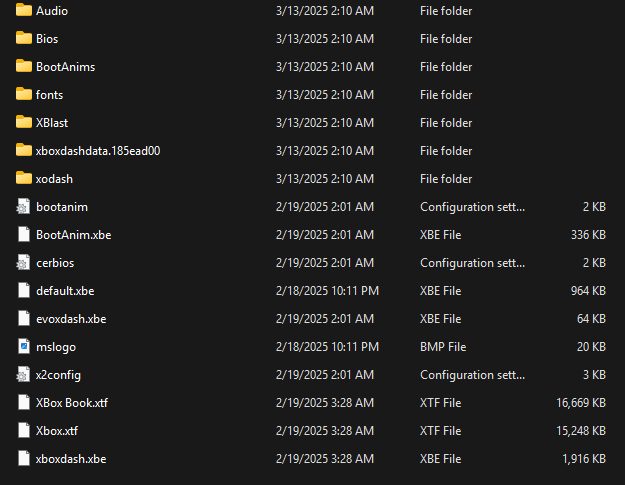
Once I reformat for Stellar in FatXplorer will the C and E partitions copy over normally or will i have to remove any and all Cerbios info that's in them? Basically i have XBMC, Emustation, etc. all on the E drive which should be fine, but my C drive contains boot anims, logo's, configs, etc. Image below shows how it looks. I just want to have a smooth transfer so I don't have to go too wild with changing things.
Stellar doesn't even look at Cerbios stuff, no reason to delete it unless you want to.
-
39 minutes ago, ForceLikeObi said:
If not I'll just have to rebuild these SSD's after reformatting them for Stellar in FatXplorer.
How big are they?
-
-
5 hours ago, peterpop said:
I get the "No valid Flash device Detected!!!" and I immediately thinks its because the modchip is active and hides it. Am I correct in that assumption?
No.
You are correct about the TSOP not being accessible after booting a BIOS from a modchip.
However, the OpenXenium modchip cannot be flashed using XBlastOS or other BIOS flashing apps (e.g., Evoxdash). The XeniumOS is used to flash (add a Launch item) a modified Xbox BIOS to the Xenium/OpenXenium modchip. As well, the XeniumOS is updated when the Xenium modchip's recovery switch is set to recovery mode after placing a XeniumOS recovery.bin file in the root folder of the E drive and power cycling the console. The recovery - XeniumOS update - will be executed from the current XeniumOS on the modchip.
-
 1
1
-
-
On 3/10/2025 at 4:39 PM, Gold_Phoenix said:
I honestly have no idea whats wrong tbh, I'll probably try and go over all the ram again tomorrow but other than that i dont have a clue.
Look over the rest of the motherboard for solder splashes. A small bit of solder may be connecting two traces together that should not be.
Edit: Verify that the trace inside the LPC Debug port outline is not cracked/broken.
See: Fixing flashing red/orange tutorial - Difficulty 8/10 - xbox-hq.com Xbox Tutorials
-
1
-
-
Verify that the the PCI_RESET# signal is reaching all SDRAM chip's CKE pin - pin # 53. It is not easy to trace this signal since it is not a direct connection from the MCPX to the RAM chips. This signal originates at the MCPX chip then connects to the LPC debug port - pin 5 then is split to several level shifter/buffers before connecting to the RAM chips. It is used to reset other peripheral chips on the motherboard too.
-
1
-
-
On 3/10/2025 at 3:49 PM, Gold_Phoenix said:
I've also learnt that on a normal BIOS, it will error unless exactly 64mb or 128mb of ram is installed, I don't know if this applies to promethos, but i know for a fact it doesnt on Xblast OS.
I believe only XBlastOS will boot on a RAM upgraded modded Xbox without all of the additional chips installed and working.
-
-
On 3/12/2025 at 10:16 AM, rubbyboy said:
Oh ok, so Hexen should remove all of the hacked stuff installed...but also the bios of the console?
Don't...it will not remove a bios from the console. A BIOS is required - stock or modded - for the Xbox to run.
QuoteAlso, I haven't opened the console yet, but should I remove any contact bridges or modchip installed or should I leave them in place?
Leave it.
-
On 3/11/2025 at 10:01 AM, rubbyboy said:
Hi, I recently bought an Xbox, and I noticed that had EvolutionX installed.
Being a very old softmod,Evoxdash is not a softmod. It is a replacement dashboard that can be used on a soft or hard modded Xbox.
-
On 3/11/2025 at 1:30 PM, rubbyboy said:
Yeah the Microsoft logo appears every time I boot the system.
If I keep pressing the power button for like an extra second, it boots into Evolution X.
When you power on the console, first do it with a quick tap of the power button. Does it boot into the stock MS dashboard?
Next, hold the power button for a second when turning on the console.
Do you see an Evox shield in the upper left-hand corner of the screen?
And, it boots into Evoxdash?
Download the evox.ini file from the C drive. Open it in a text editor and find the Current= line.
Post the hexadecimal value after the equal symbol.
Edit:
If so, your console is hardmodded. A modchip is installed.
-
The BIOS/Kernel is stored in the TSOP flash memory chip or custom Xyclops chip on the motherboard. The kernel is extracted from the data stored in that memory device. When extracted, it is copied into RAM and executed from there.
-
 1
1
-
-
The BIOS/kernel was never upgraded on the Xbox. The BIOS/kernel installed from the factory is what it kept. Only the dashboard was updated.
-
12 minutes ago, Andrew smith said:
Yeah but any idea which pin I can desolder without removing the added ram so that xblast doesn't see them?
Xblast works no problem same as smartxx menu and ox menu.
Plus smartxx v3 menu has ram tester and its all successful
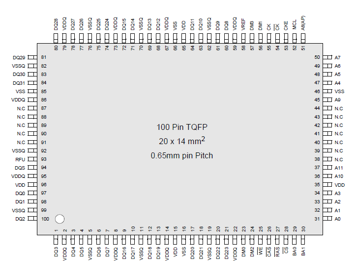
Try pin 53 - CKE - on the 4 extra DDR SDRAM chips.
-
Many pins on the end of the Xbox's DDR SDRAM chips have no connection (N.C). Pin 8 down on that end is one such pin. Which is the right-hand side of the following image - pin 38.
-
Xbox-Scene.com Xbox Xecuter 2.0 2.1 2.2 2.3 2.3b 2.6 Lite Modchip pictures
Scroll way down to it.
Xecuter 2.0 Lite
-
1
-
Board Life Status
Board startup date: April 23, 2017 12:45:48
problems after hdd upgrade
in Hardware Mods
Posted
Strange. Seems like the flash memory chip's identification bytes are not accessible. The chip is not writable or of a type that Evox is NOT capable of flashing.
Does Evox.ini contain the Flash line to ID an SST49LF020A?
Flash = 0xbf52,"SST 49LF020A",0x40000
And, what is the value of the Current= line?