

SS_Dave
-
Posts
4,719 -
Joined
-
Last visited
-
Days Won
268
Content Type
Profiles
Forums
Calendar
Store
Posts posted by SS_Dave
-
-
Unlock both Drives I never relock them. But I don't use softmod's
Unlock the 500 gig and put it aside then when you fitt in the other box it should work If the 8 gig is going in the from the xbox it came from just put it back in and it will fireup and should be good to go.
SS Dave
-
That is a bit strange between the to games
I just had a quick try on Splinter Cell and I found the controler slow to respond. I also tried with Splinter Cell - Double Agent and I had to remove the extention lead from the controler and use a differant controller to unlock the handcuffs at the beginning. They are both OEM contrers the had to use the S type to unlock it as it keeped saying plug in controler and press start with the full size one.
I also tried Metal Gear Solid 2: -Substance with both controlers with the extension lead inline with no probs.
I suspect it's a timing problem.
SS Dave
-
Are both Xboxs modded ?
If not soft-mod the other one.
Then you can unlock the drives
If yes you need to do that on both box's then you should be able to swap the drives.
SS Dave
-
Capacitors are a bit like a rechargable battery so it may be ok. Because of the large value of the clock capactior I would asume there is some sort of current limit on the charging circuit so having the box on for several hours would be long enough to fully charge it.
All good then.
SS Dave
-
 1
1
-
-
The power supply has nothing to do with PAL/NTSC it's only that it's 220/250 volt as aposed to 110 volt and to suit a version 1.6 mother board.
SS Dave
-
Hello Hector.
Although the cap looks ok it's properly on it's way out.
A 1.6 Xbox won't boot without the cap so you can't just remove it, you could try replacing it.
It's not something have seen yet but insaying that in all versions of Xbox's all the cap's are getting old and starting to dry-up and causing problems
Years ago I found as I was soldering any capacitors that where starting to leak I would get a strange strong smell as I heated the legs on the offending cap.
As my 1.6 Xbox has internet and sets the clock on boot so I have never noticed the time out as do all the other Xbox's I have in use.
I removed the cap's from them so to prevent damage to the PCB and they are also set on boot to set the clock automaticlaly from the interweb.
As the cap is only for short term memory meaning properly only hours anyway as apposed to a Sony PS2 that I powered up 2 years later and the clock was only 5 minutes out but the PS2 has a large button battery for backup.
Cheers
SS Dave
-
1
-
-
Welcome
If it was me I would fit a mod chip then you won't have to worry about stuffing around with softmod's, Work Miss Google for Aladdin Modchip.
Ebay around 4 usd or AliExpress about the same.
Search for here for softmod that will give you some reading if you don't want to go the modchip route.
Don't be afraid to ask question's
Cheers
SS Dave
-
13 hours ago, neighbor said:
really?
Yep
I have been working on CD/DVD players longer than I would like to say.
Sure it makes noise while in use.
On power up the lazer turns on and it spins the disk looking for a boot file to load but if no disk is detected it spins the spindle motor/disk clamper assembly backwards for a split second then foward for a second just to double check it then shuts down(I even just pulled the lid on a Xbox DVD drive to confirm it.) untill you open the tray or reboot the Xbox..
So removing the DVD drive is not going to help reduce noise unless you want to prevent the DVD drive from been used.
If you have had one making noise constanly then it was probably faulty.
I have also tested some Samsung,Thomson,Philips drives and they all do the same.
Yes a SSD would reduce noise but you still need some forced cooling(A FAN) which tends to make more noise than a good hard disk.
SS Dave
-
2 minutes ago, neighbor said:
even if there is no disk inside, it still checks for a disk and makes noise.
For a second or 2 on power up only.
-
On 7/26/2019 at 6:42 AM, neighbor said:
can not recommend one, but can say an SSD and DVD drive removal - would reduce the noise.
How can removing the DVD Drive reduce noise as when there is no disk in use it's sitting there doing nothing
-
Well Done and congratulations that wire link you have put on PCB this time is much better.
You should add some flux to the LPC pins and reflow the solder as some look a bit susspect the common name for a conection looking like that is a dry joint which can fail easly with heat/cold and vibration. You can apply a little bit more heat compaired to the other tracks have a look at the power connector pins and you should get the idea.
Give the entire board a clean and reasamble and then enjoy!
Cheers
SS Dave
-
9 hours ago, Ryzee119 said:
Love the old veroboard modding. This is awesome and definitely a very unique xbox now! great job.
Thank's
I prefer the unhacked up look with the mod cons A bit like a sleeper car.
-
10 hours ago, KaosEngineer said:
All the solder on the pin header connections to the LPC Debug port are just sitting on top of the pin not making a connection to the motherboard. The solder should flow into and around each pin inside the thru holes of the motherboard.
If it FRAGs with the modchip connected, D0 is grounded forcing the loading of a BIOS from the LPC attached flash memory device on the modchip. However, the BIOS is not loading thus the FRAG.
Reflow all of the LPC pin header solder joints to make a good connection to the motherboard not a ball sitting on top of each pin.
See: https://learn.adafruit.com/adafruit-guide-excellent-soldering/common-problems
That maybe the case but he needs to repair the damage to the PCB 1st. Lets get it working then look at modding it.
-
1
-
-
If you have one xbox thats works ok have you conpaired settings like region, time zones, etc
Whats the name of some of the games?
-
What BIOS are you using?
-
Try setting 480P to ON
-
Have you tried setting PAL-60 to No
The Pal format is 50 hz and at the momnet you have 60hz\
SS Dave
-
Yes you can higher in voltage so from 6.3 volt to 10 volt is fine.
SS Dave
-
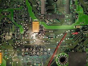
Good to here you got it going and I think it's going to live. It also looks like you removed some of the excess solder from the LPC port
Here is part 2 of my Tutorial with pictures.
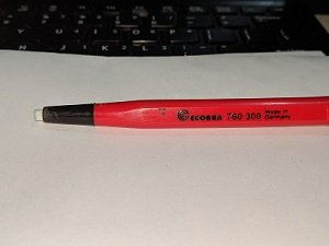
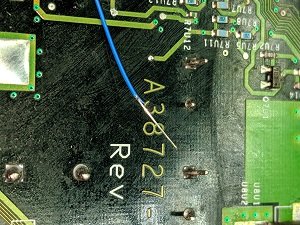
1st step Clean off the paint.

I cheated and used a Glass fiber pen to do that but gentley scraping the track is ok you only nead to remove the paint.
2nd Step Add flux to the board
3rd Tin the trace
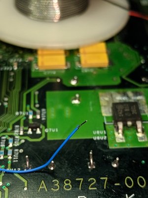
4th Prep the wire you are going to use
5th Tin and trim the wire. I should have trimed it a bit shorter
6th Lay the wire on the tinned trace and apply heat.
7th Clean up the PCB
Now rince and repeat for the other end.
Once you have tested it and your happy a small dob of hot melt glue or even a dob of super glue to stop the wire moving. Not on the solder joint say 5 to 10mm(1/4 inch) from the solder joint.
Once you have it up and running I suggest you use the D0 point on the other side.
Then when it can read backup disk's think about putting on the TSOP flash links even if you use conductive paint and reflash the board and keep the chip for a your next one. A search will fill you in how to do that.
The best thing I did was get a memory card and the 007 agent under fire game.
Easy add the TSOP flash solder links copy game save to Xbox from the memory card then insert the 007 game in drive and reboot the Xbox when game has loaded load the saved mission then less than 5 minutes later it's reflashed.
Any way let me know how you get on with the repair.
Cheers
SS Dave
-
Have you had a look at the video setting via MS Dash?
SS Dave
-
And let that be a lesson to you.
Good to here it's alive!!
Post a pic of the repair if you game
-
Sorry for the long winded post it's more of a Tutorial on geting out of a minor stuff up.
All is not lost
I have had PCB's droped on my repair bench with a sh!t load more damage than that in the 40+ Years I have been a tech.
1st up carefully remove that wire and bin it.
Clean the around where you have been working I use this stuff with an antistatic brush but an old tooth brush will also work.
A cotton bud (quetip) is ok for where you had the wire is if your scared.
You can also clean the whole PCB with the same stuff. Make sure it's dry befor powering it up a heat gun on low or a hair drier will speed that up. Cleaning a whole board like a xbox with a quetip is for beginers. Boards go though a full autrasonic bath in production so a light scrub with Isopropyl is nothing. In a pinch you can use methylated spirits.
2nd Go and get some Kynar 30AWG wire.
While your getting the Kynar wire get some Solder wick, 0.8mm solder and solder flux paste.
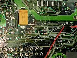
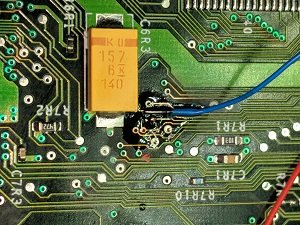
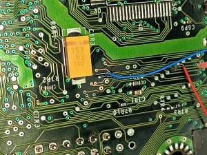
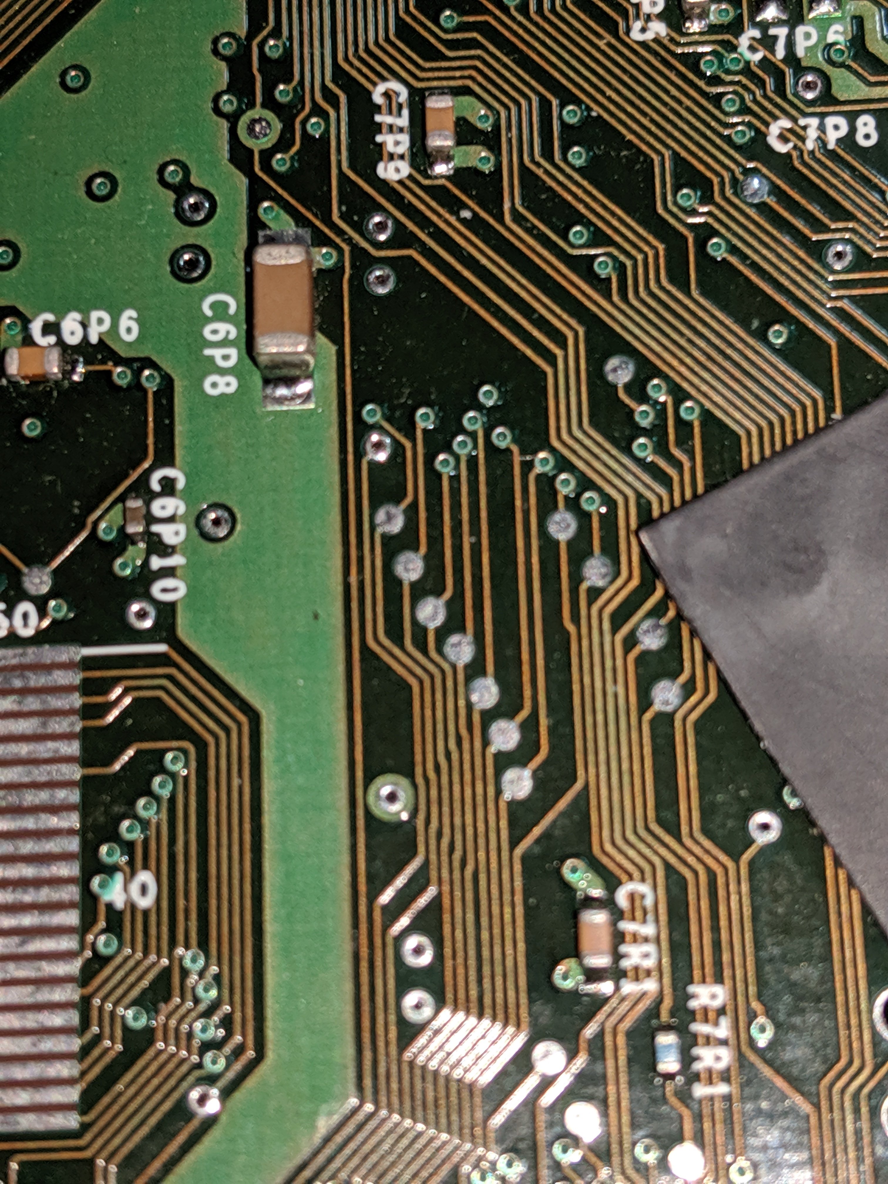
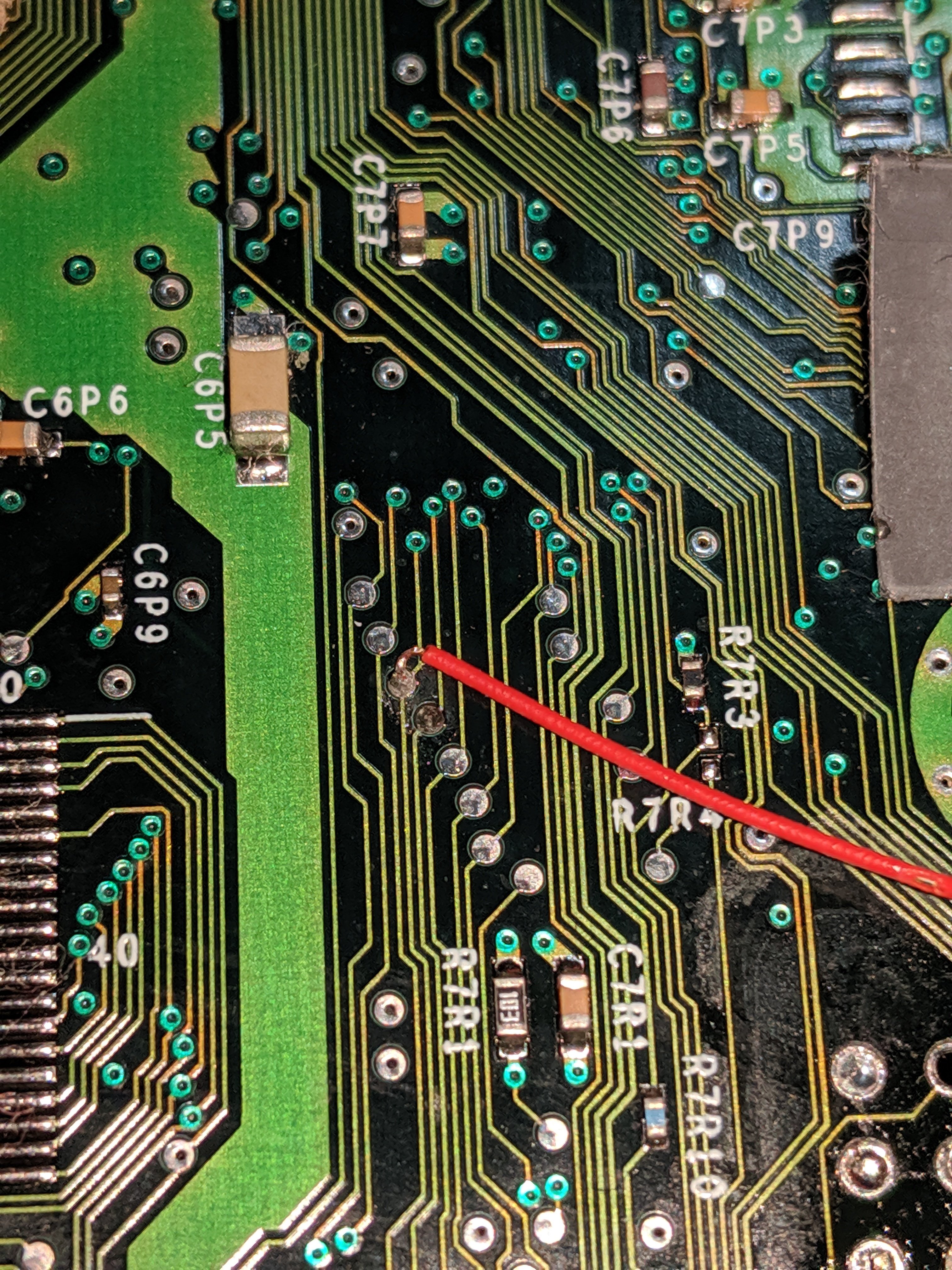
Look at this pic below if you solder a wire from where you had your wire at the red mark at the top to the trace beside the red mark at the bottom that will repair the board.
If you follow where you have soldered the wire along the track you will see what i mean.
It's the trace on the corner of the yellow capacitor.
A light scrape of the pcb to remove the greenish paint ( I mean light you only want to remove the paint so you can see the silver/copper track) then add flux, then tin the trace (add a small amount of solder to the track) {work Dr Google for solder tinning } now tin the wire now hold the wire on the tined trace and apply heat. Job done.
The next 2 pics is from a Aladdin install manual
To attach the D0 wire to the PBC on the top using the technique above or you can add the D0 wire to the same wire you repaired the track with.
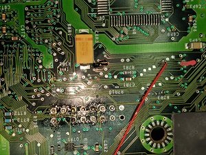
Using the solder wick remove 75% of the solder around the LPC port adding some flux will help use Miss Google again if your not sure on using solder wick.
Now remove the clock cap (do a search)
Give the PCB a good clean and go over your work with a magnifying glass and redo anything your not happy with.
Once you have compleated the repair and it's all working and your happy with your self give your self a pat on the back and post us pic of your work.
A hint DO NOT work on this type of repair when tried, stressed and have plenty of light. Also don't rush it just take yor time.
If you get stuck or are not sure if your doing it corectly just ask.
Good Luck
Cheers
SS Dave
I am just blowing my own trumpet here. This is pic of one of the PS2 Mod chip's I fitted sometime ago.
-
And yes the pad you have soldeered to is ground.
SS Dave
-
1st up the trace is damaged and will need to be repaired
You will need to link the trace either side of where you tried to solder too.
2nd try using a thiner wire single strand wirewrap wire is perfect and any reason you have the D0 going to ground and not to the D0 pad on the mod chip.
3rd Please clean that mother board and not so much solder on the LPC port.
Cheers SS Dave


Board Life Status
Board startup date: April 23, 2017 12:45:48
Splinter Cell Controller Problem, I Need Some Feedback, (Original Game)
in Games
Posted
That is a bit strange between the two differant games
I just had a quick try on Splinter Cell and I found the controler slow to respond. I also tried with Splinter Cell - Double Agent and I had to remove the extention lead from the controler and use a differant controller to unlock the handcuffs at the beginning. They are both OEM contrers the had to use the S type to unlock it as it keeped saying plug in controler and press start with the full size one.
I also tried Metal Gear Solid 2: -Substance with both controlers with the extension lead inline with no probs.
I suspect it's a timing problem.
I also have played plenty of MAME games with the same controler config without any problems.
It should not make any differance this box Ver 1.6 X3 with LCD and 2tb hard disk proberly 85% full using Component video and coax audio out . If i get a chance I will try on a ver1.0 box with a smaller IDE drive.
SS Dave