
.jpg.d30ae03ca9aec5699db7b163a5434573.jpg)
Prehistoricman
-
Posts
110 -
Joined
-
Last visited
-
Days Won
9
Content Type
Profiles
Forums
Calendar
Store
Posts posted by Prehistoricman
-
-
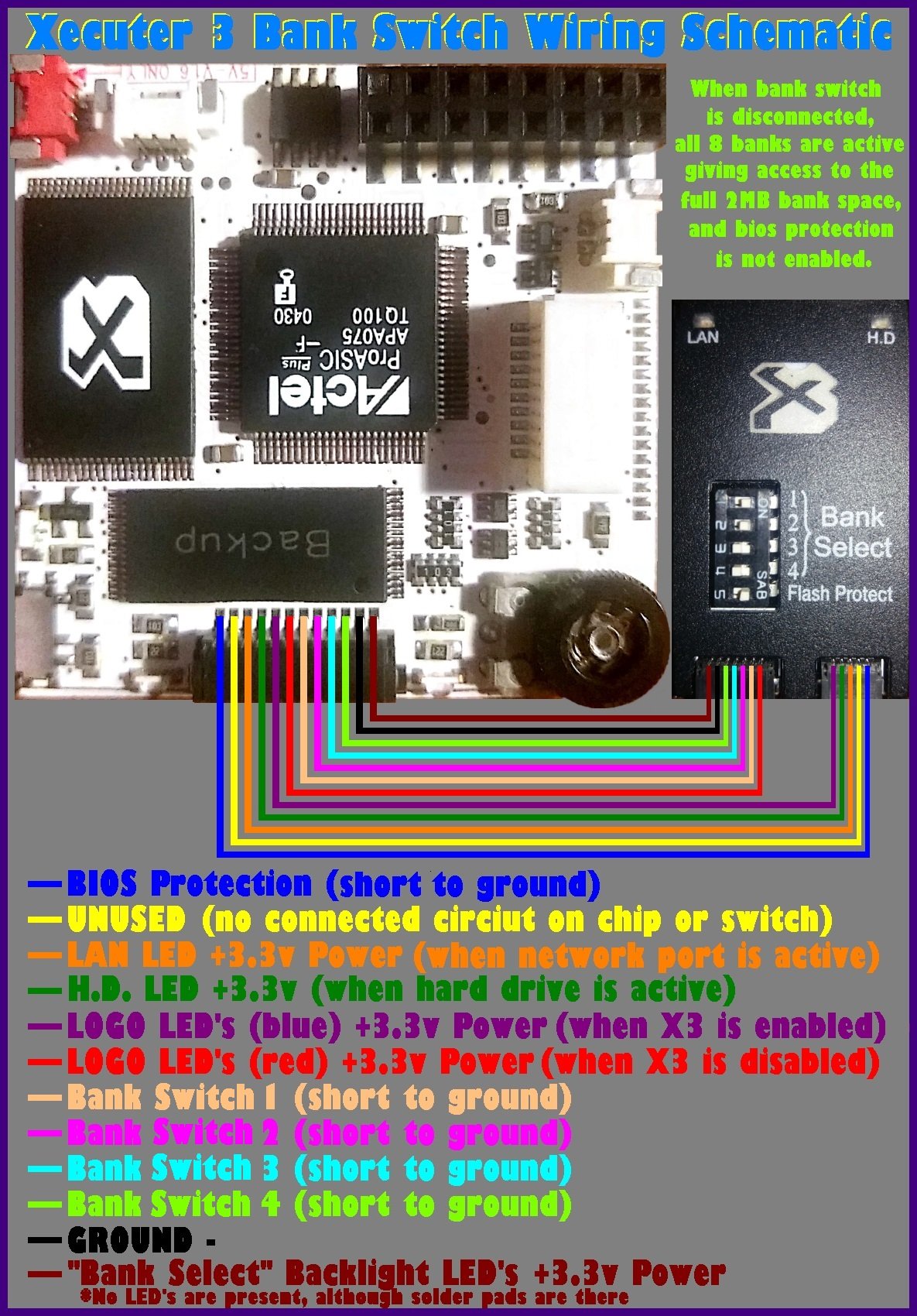
Yeah you can make your own. It's just a PCB with switches and LEDs. Hardest parts are the cable and the vanity cover. If you find out what connectors and crimps are used, let me know because mine has some dodgy wires.
This is a wiring diagram I found online. The LEDs may require series resistors, not sure.

-
 1
1
-
-
Doesn't the fatal error screen say that there is an FTP server to connect to?
-
 1
1
-
-
Have you tried that BIOS with a modchip before?
Did you use the EvoX dashboard to flash the TSOP or something else?
-
On 7/30/2022 at 11:51 PM, zzattack said:
On the acquisition front, the last batch of 4 xboxes purchased were advertised as good working condition, but in reality came with a bunch of non-disclosed issues: 3x non-functioning dvd drives (1x tray doesn't open, 2x won't read discs), 2x clock cap damage, 1x missing HDD (seriously!?). I'm not even gonna bother contacting the sellers since a) I barely know for sure which console came from which seller, b) it's all fairly easy to fix, and c) they've all come across so illiterate and hostile in their communication I halfway expect them to reply with threats if I'd merely suggest they sold me less than was advertised. Powering through.
There is some reverse psychology in play. I got an 'untested' Xbox which the seller described as having DVD drive issues. Come delivery day, it powers up fine, the DVD drive is fully working and plays the free splinter cell disc that was inside! I suppose the postal service applied some percussive maintenance.
Or it's just random/luck. You can increase your odds by choosing listings with good pictures and some description.
-
3
-
-
You still have the inductor symbol for the resistors.
-
1
-
-
Your dump is almost identical to the 'HitachiLG8050' firmware on xbins.
What's the drive model that it came from?
-
In your first post, you said that the blue wire was 0.1V. This is normal because the signal comes from the motherboard. Plug in the power connector and re-check this signal.
You also measured continuity around the FAN5059M chip. The readings for pins 2 and 20 are abnormal, but they are to be expected when you measure the other shorts to ground. Essentially you are measuring the same wires.
50 minutes ago, BillFences said:Could you tell me their codes on the PCB? And how I can figure if they're broken?
U2T1 (the FAN5059M chip) which you could desolder and re-measure the resistances. I don't know about the transistors. You could try desoldering the switching inductor L2F1.
-
I get about 30 ohms for C1E2 and the caps under the CPU. 155 ohms for C1G10.
This sounds bad for your CPU but the issue could still be some other component involved with that power rail such as the switching regulator controller or the switching transistors.
-
What resistance do you read as "shorted to ground"? If it's just the continuity beep, then you can't trust this because it has some arbitrary threshold.
-
Recently I got a sheet of tinfoil and cut a memory sized hole in it. Then place it on the board and adjust the foil until it sits flat to the board. This will redirect hot air away from any components. Then you can use any source of hot air (I used a heat gun and didn't cause any carnage). Alternatively you can get Kapton tape which is heat-resistant.
-
1
-
-
Yeah that doesn't sound good. You can try desoldering the suspect resistor and unwrap it to see its value. See if you can find a replacement and maybe that will fix it.
While you have the PSU out, check the resistance between pins on the heatsinked devices. They are usually 3-pin transistors and these often fail short-circuit. Also measure the resistance of the fuse which is the brown cylinder next to the AC in plug.
-
20 minutes ago, nerdbombing said:
I was thinking about that the other day when we talked about thermal vision. So the PSU is turning off, overload or whatever, so the component wont get hot. I assume you're talking about using a bench power supply or something that will not 'turn off on safety'?
Yes
-
1
-
-
You can inject voltage, aiming for a decent power consumption like 5 watts, limited to 5 volts of course, and feel the board/chips with your hands. If you can't feel anything, increase current and keep going.
-
2 minutes ago, tssfka said:
The voltage black to red was 0.3V initially but quickly dropped to 0.03V and stayed there while reading.
Can you start making the measurement before plugging in the Xbox, then plug it in and see if it goes to a higher voltage?
-
10 minutes ago, Donnie-Burger said:
This is for anyone attempting this for the first time:
Ordered some ram from china new and as the one module I installed last night worked it was a pain in the arse. For some reason the new samsung chips from china have shorter legs (Or slightly thicker module) making it real tight. Spend 2 hours installing one.
Spent 20 min installing one from a donor board. Night and day degree of difficulty.
I suppose they are just that bit cheaper with shorter legs. Gotta love China

-
1
-
-
Can you unplug the Xbox from the mains, disconnect the motherboard power connector, wait at least a minute, then plug it back in and measure the voltage between any red and black wires on the connector?
That R10 resistor should probably not read open circuit. It may be a fusible type and broken open. You can remove the heatshink carefully to see if it looks damaged.
-
4 hours ago, nerdbombing said:
I agree, as I have pin 6 & 15 (5v & 3.3v) of the LPC showing continuity to ground.
This is normal, depending on the multimeter. On my 1.6, measuring resistance of 5Vsb to ground shows it rising from 0 up to 150 ohms after about 6 seconds. That is the large capacitance charging up loaded down by everything on that rail. Meters have varying thresholds for what they consider continuity before bleeping.
Exactly what resistance do you have to ground on those LPC pins?
-
6 hours ago, nerdbombing said:
PSU is good, voltage is reading the same on both PSU's (not sure if I showed the second, but it is the same as the first) https://youtu.be/oX9MhvWFRIs
That's a very useful video. I see there is no voltage present in the Xbox as long as the power connector is plugged in. That's going to be some over-current detection shutting off the power supply. Basically you have something short-circuited on the board. The expert repair man at NorthridgeFix always diagnoses shorts by injecting voltage with a power supply and seeing what gets hot. I don't suppose you have a thermal camera?
-
1
-
-
32 minutes ago, zzattack said:
Interesting upgrade. Are you looking into using different RAM types entirely, such as DDR-333/DDR-400?
I'm gonna see if I can complete a first 1.6 with 128MB + 1.4GHz combo.
I was thinking about it, yeah. However I'm not sure it the system would support the RAM clock being faster than the NVCLK at 233MHz. I'm also not sure how to change the timings for the memory. DDR-400 would require a higher CAS latency, for example.
-
@nerdbombing Are you sure you read 4V on the orange wires and not something closer to 5V?
-
1
-
-
Yep with the reading at the inductor, this really sounds the same as the other topic. I just don't know where the 5V from the power connector goes and gets stopped.
-
1
-
-
6 hours ago, xgekox said:
hello,
first of all great job! I wanted to ask you if you also had the source code of the new version of xblast (0.60) which if I understand correctly, works like 0.56 but in addition it has support for xbox 1.6, right?
Thanks
I wasn't going to publish the source since it's barely any different from the original. And I don't want responsibility
")
To reproduce what I have in 0.60:
- Install a git client. I use TortoiseGit since it has a nice UI
- Clone the git repo from https://bitbucket.org/psyko_chewbacca/lpcmod_os/src/master/
- Roll it back to version 0.56 to fix FATX and networking bugs
- Modify menu/textmenu/ToolsMenuInit.c as described in the tutorial
- Duplicate line 1111 in etherboot/drivers/net/forcedeth.c. This line should say pci_push(base);
- Change the version string in include/config.h
-
3
-
This is just a show and tell post.
While doing my other Xbox research, I am powering on and off the Xbox a lot. I also do the power + eject sequence to load the backup bank on the Xecuter X3 a lot. I was thinking this would be slightly more convenient if I had a remote control so I found some spare IR receivers and a small board with a microcontroller on it and got to work.
The install is pretty stealthy. It's on the left of the front panel.
Microcontroller is on the back of the board. Connected up with thin enamelled wire from a transformer. Board is held in with Earth's greatest material: hot glue.
I used the spare pin on the front panel connected to carry 5V to power the thing. Series resistor to limit the current or act as a fuse in case it shorts out.
I programmed it to use volume up and down on a generic remote for power and power+eject. This sounds inconvenient but I never use those buttons.
-
2
-
-
5 hours ago, clueless said:
Do you have any links or guides for doing this?
Sorry no. It was just an idea.


Board Life Status
Board startup date: April 23, 2017 12:45:48
Xbox 1.6 with samsung drive and soft mod Error 12
in Repair
Posted
With either the diode or resistance test you can test the cable from end to end + the connectors by plugging in both ends and measuring between the solder points for the connectors.