
.jpg.d30ae03ca9aec5699db7b163a5434573.jpg)
Prehistoricman
-
Posts
155 -
Joined
-
Last visited
-
Days Won
21
Posts posted by Prehistoricman
-
-
6 minutes ago, Shmingers said:
Hi, I used OGXbox Installer 2021. I didn't think to use any other tool...never had an issue like this before. Would it be worth trying to flash with something else? Hexen or such?
Should be fine but I meant to confirm if the flash is really working properly by flashing a non-EvoX BIOS and run it on your 1.1. Just to see that it's no longer booting evox and thus the flashing worked.
-
What are you using to flash it? I wonder if the flash is not working properly despite it saying it's good. If you flash it with something different like stock microsoft or cerbios, does the expected bios boot then?
-
4 hours ago, emiliano said:
I tried the masses everywhere always same result
With 340A I have 3.6v on rx and tx
With native serial 2.4vWhen you run the script or GUI, does the Xbox stop responding to the power button? It should.
-
 1
1
-
-
17 hours ago, emiliano said:
I tried everything. I connect the xbox with its power supply without turning it on I connect rx and tx (about 3.6 V). doing this it recognizes the connection but the deletion fails. on the other hand if I also connect the adapter ground to the card, at this point it doesn't even establish the connection
Try connecting your ground to the other side of the C7C7 cap (the one that DEBUG is wired to).
Can you measure the RX and TX voltage after connecting to the Xbox and plugging it in? 3.6V is unexpected.
-
1
-
-
2 hours ago, emiliano said:
Hi.
I have the problem
Xyclops A-A02
It always gives me the error "erase failes"
I connect with only the rx and tx on the board and power the board with its power supply
I also tried with xyclopmodgui 0.51 but this does not connect.
I use rs232-usb ch340 adapter
I also tried with ch341 but the same
C:\Users\Xbox360\Desktop\1.6>python xyclops_flasher.py Cerbios.bin com12
Xyclops communication established
Ready to erase? (y/n)
y
Erasing...
Erase took 0.000 seconds
Error: erase failedYou have a connection problem as the GUI says. The script is less stringent in determining if a connection is made.
Check ground connection and voltages of the RX and TX.
-
25 minutes ago, steve1 said:
hi out of interest can I flash the chips off the motherboard if i connect the right pins to v3.3 gnd txd rxd i have 20 dead 1.6 s what i have all the cyclops chis removes
Never tried it but you'd need to hook up the some extra pins to power the chip up
-
1 hour ago, steve1 said:
hi i am tying to do this i got python 3.13 from the app store downloaded the git hub put the xbox smc master folder on my destop put cerbios in the cyclops folder ran cmd from xbox smc master folder put in the command
python xyclops_flasher.py cerbios.bin COM7
i get errno 2 no such file or directory any advise thanks Steve
i am using a ch340e usb serial
I think your cmd isn't at the right folder. Easiest way is to open the folder where xyclops_flasher.py is in file explorer, shift + right click empty space (not on a file), click "open PowerShell window here". Then you can run the python command.
-
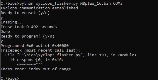
2 hours ago, d3cka2d3pwood said:
Hi, I nearly did it but get the following error. Has anyone else had this or know how to solve?

It means there was a timeout while trying to program. Not a python installation issue but a setup issue. Check all connections especially your ground connection. See if you get the same error every time you try the script.
-
27 minutes ago, swordeye2 said:
Thank you! So this image is consistent to the instructions given for the Xyclomod?
No, that image shows a different arrangement.
I really don't recommend the AV port option as stated in the tutorial on xbox-scene. I haven't been able to edit my post here.
-
BIOS patcher updated for v1.6 compatibility!
I'm not aware of anyone who's tried out this mod on a 1.6 yet but now it's ready for when they do.
-
2
-
-
Have you considered using the test points? All the flash chip's pins are broken out to test points on the back side of the motherboard.
-
3
-
-
The small (0402) caps are 10nF, medium (0603) ones are 100nF, big (1206) are 10uF.
-
Check the back side of the board directly under bank 2. If there's something like a short circuit there, then it will still cause bank 2 problems.
-
A while back, I read some Xecuter discussion from when the 1.6b started being seen, and people were getting issues including the Xbox no longer working. It feels incorrect to say but it sounds like RAM can be damaged by a BIOS that doesn't trim it correctly on a 1.6.
2 hours ago, Petrolhead said:XblastOS v0.64?
Yes but more specifically the RAMTESTER version. See the readme https://bitbucket.org/prehistoricman/lpcmod_os/src/master/README.md
-
1
-
 1
1
-
-
1 hour ago, Bowlsnapper said:
Do both these chips have any kind of datasheet? Something that would explain why the mod only works on the A but not the B?
Hell no!
-
1
-
 2
2
-
-
New Xblast OS 0.64 available: https://bitbucket.org/prehistoricman/lpcmod_os/downloads/
Fixed the 256MB test freezing when less than 256MB is detected (sorry!)
-
5
-
-
1 minute ago, Petrolhead said:
@Prehistoricman Thank you
")
Noob question: got an link to a 3.3V USB to UART adapter that works? (About TX 1k resistor)
Im gonna order one .
Yeah any that looks like this https://www.amazon.co.uk/AZDelivery-FT232RL-Adapter-Arduino-Raspberry/dp/B01N9RZK6I/ref=sr_1_11?sr=8-11
-
1
-
1
-
-
PSA: If your Xyclops is marked A-B01 then this mod currently isn't going to work. We're trying to find out why and fix it.
4 minutes ago, Bowlsnapper said:Are the TX and RX on the AV port, presumably, so MS could plug in a custom AV adapter and just flash without soldering? It makes perfect sense.
So it turns out that they are blocked on retail boards, but looks like dev kits are missing the resistors. So it was for development of the xyclops presumably.
-
1
-
-
32 minutes ago, Skoot said:
Big thanks to Prehistoric Man.
Ive reflashed four xyclops no issue. i had an issue with a fifth where the chip would erase but then throw an error saying it wasnt erased.
It would be ideal to add that the Uart adapter requires grounding to the motherboard or metal sheilding. Also Pyserial is needed to be installed for the script to work
Thanks! Does that 5th xbox's xyclops chip have A-B01 written on it? Does the xbox have hynix RAM? We've not been able to flash a v1.6b yet.
I've added a check in the script for pyserial, and good point about grounding.
-
Correction: you can't do this without opening the Xbox. The mobo has a 0-ohm resistor tying those AV pins to ground

Sorry for the false claim.
-
2
-
-
I'll document the serial protocol and internal registers in the repo soonish: https://github.com/Prehistoricman/Xbox_SMC/tree/master/Xyclops
But the Xyclops class in xyclops_flasher.py contains a lot of the useful commands already, so if you're crafty with python you can already use that.
-
3
-
3
-
-
It has long been thought that the Xyclops chip, which contains the BIOS on a v1.6 motherboard, is not flashable. However I recently discovered it has a serial port with a variety of interesting commands. It supports dumping the BIOS as well as the Intel 8051 code that runs the SMC functions of the chip. And just like the other Xbox versions that have the TSOP flash, we can reprogram the BIOS on the v1.6.
In one way this mod is better than your typical TSOP flash because it's easy to recover from if you screw it up. The serial port will still be available.
Tutorial
Required items:
- 3.3V USB to UART adapter. You can find many of these available online at very low prices. See if you can get one that has a TX resistor value lower than 1k because the Xbox's RX has a 1k pulldown.
- v1.6 Xbox with Xyclops marked A-A02. A-B01 is not supported.
- Soldering iron
-
Either the GUI for Windows or the command-line script:
-
GUI
- Download XycloModGUI by OGXLABS https://www.ogxlabs.com/xyclomodgui
-
Script
- Python installed on your PC
- Download the script https://github.com/Prehistoricman/Xbox_SMC/blob/master/Xyclops/xyclops_flasher.py
-
GUI
- A 256KiB BIOS bin file
Steps:
-
Connect your USB to UART adapter to the Xbox. This can be done either by connecting to the AV port, or by opening the Xbox and using internal connections.
-
Internal connections
-
Xyclops pin 29 is DEBUG. Wire it to the 3.3V standby voltage.
-
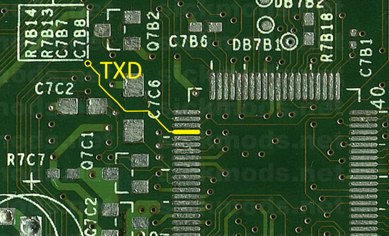
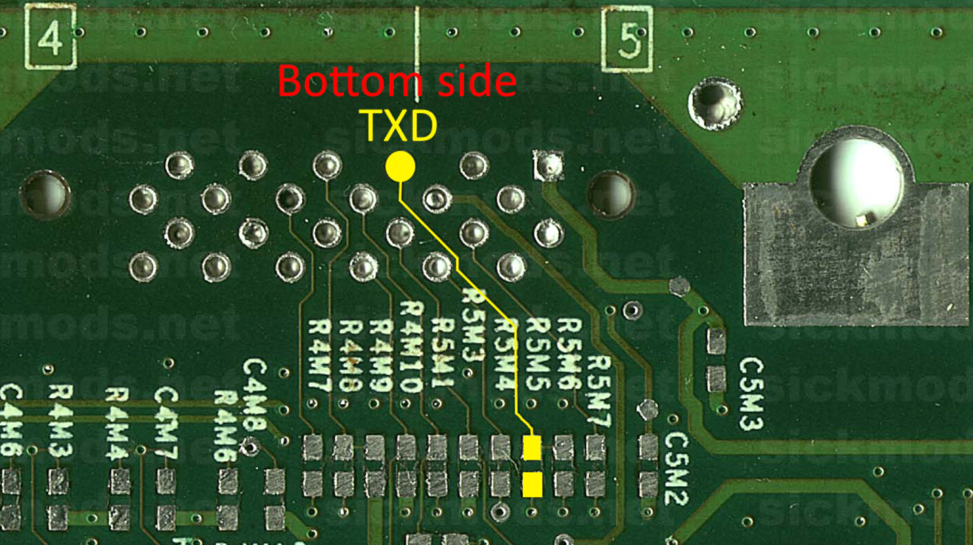
Xyclops pin 64 is TXD. Wire it to the adapter's RX pin. Either:
-
Near Xyclops:
-
OR under the AV port:
-
Near Xyclops:
-
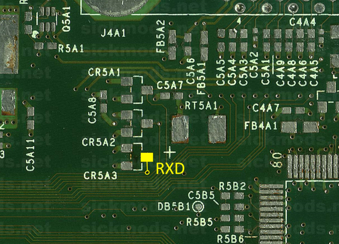
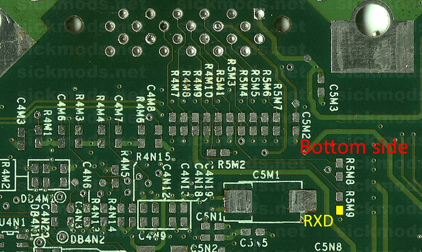
Xyclops pin 63 is RXD. Wire it to the adapter's TX pin. Either:
-
Top side, near AV port:
-
OR under the AV port:
-
Top side, near AV port:
- Connect ground to the adapter's GND pin. You can use the xbox metal case, any screw holding the motherboard down, or pin 2 of the LPC header (see pin layout here).
-
Xyclops pin 29 is DEBUG. Wire it to the 3.3V standby voltage.
-
AV cable - not advisable!
- See AV plug diagram here https://xboxdevwiki.net/AV_Cables
- Pin 5 is DEBUG. Wire this to 3.3V.
- Pin 18 is TXD. Wire this to the adapter's RX pin.
- Pin 6 is RXD. Wire this to the adapter's TX pin.
- Remove resistors below the AV port: R5M3, R4M10. This will affect the video mode recognition and can prevent normal display, so they should be replaced after the mod is complete.
-
Connect any ground pin (such as pin 6, 7, or
 to the adapter's GND pin.
-
Internal connections
- If you cut LFRAME to do a modchip install, you will have to reconnect it.
- Plug in the USB. It's better to do this before powering on the Xbox
- Plug in the Xbox. It can be left in standby.
- Identify what serial port your adapter has. On Windows you can expect it to something like COM5.
-
GUI method:
- Run the XycloModGUI exe
- Select the COM port if you know it
- Click the Connect to Xyclops button
- Click Browse... to select the BIOS to flash
- Click Start Selected Operation to flash the BIOS to your Xbox. It should take about 6 minutes
-
Script method:
- Install Python 3 if you haven't got it already
- Open cmd, powershell, bash, or whatever the terminal is on your PC.
-
Execute the script by writing
python xyclops_flasher.py your_bios.bin COM5
to the terminal, replacing your_bios.bin with the path to your BIOS file, and COM5 with your serial port. Press enter
-
Follow the on-screen text. It should say Xyclops communication established and ask if you want to erase the flash.
- Once the connection has been made, or even attempted, you may be unable to turn on or off the Xbox. That's normal. The SMC gets frozen while the serial is active.
- The Xyclops can get upset and stop responding sometimes. If you can't get communication, try unplugging the Xbox for 10 seconds.
- If you get erase timeout, make sure you made the GND connection.
- If you can't get communication, then your serial adapter might have too much internal resistance. Identify its TX resistor and reduce it to ~500 ohms.
-
The flashing process takes about 2 minutes, and the verification (if you want to do it) takes another 2 minutes.
-
If you want to verify again, use the -v option:
python xyclops_flasher.py your_bios.bin COM5 -v
-
If you want to verify again, use the -v option:
- The Xbox power button should work again, so try turning it on.
- If you get video issues (like greyscale video) and you removed two resistors in step 1.2.5, you will need to place the resistors back.
- Disconnect the DEBUG wire for enhanced stability. The Xyclops will freeze whenever it sees any activity on the RX pin.
FAQ
-
Can we use a BIOS bigger than 256KiB?
- Not on a retail xbox. Some rare devkits may be able to do 512KiB but I have not confirmed that.
-
I ran the script and my Xbox won't turn on!
- Yes, the SMC will freeze when it receives serial communication. The script should resolve that if it exits successfully, so I must assume it failed. You can unplug your Xbox for 10 seconds and plug it back in to reset and try again.
-
Can this be done via a software method?
- Not to my knowledge, but it is rumoured to have been discovered.
- Technically the answer is yes, but it involves using the serial first and then reprogramming the SMC (advanced).
-
What else can it do?
- The Xyclops serial port is able to do a lot of low-level actions on the SMC. For example, it can 'press' the front panel buttons, change fan speed, change LED colours. It can also potentially do some hacky things such as spoofing the video cable mode, or bypassing the boot challenge (FRAG).
- We are also able to re-program the SMC which could lead to some more advanced mods for specific and niche purposes.
-
Through the AV port???
- Yeah I know right? We can't be sure why Microsoft made it this way. It's too slow for factory programming AND there's those resistors preventing it on retail units. It could definitely have expedited the development process of Xyclops, but that doesn't explain why it was left present in the retail motherboard.
-
7
-
7
-
Thanks guys
Will post a full tutorial shortly and a writeup on the technical side of course.
-
12
-
4
-
-
On 4/5/2025 at 12:14 AM, Andrew smith said:
Which one do I use to test one of the 128 upgrade chips without going into dashboard
Either XBlastOS_0.63_RAMTESTER_Stock.bin or XBlastOS_0.63.bin. The RAMTESTER version won't display anything on-screen unless you press eject though.

Board Life Status
Board startup date: April 23, 2017 12:45:48
XycloMod: flash the on-board BIOS on v1.6
in TSOP Flashing
Posted
No luck, still working on it.