

mattison1986
-
Posts
40 -
Joined
-
Last visited
Content Type
Profiles
Forums
Calendar
Store
Posts posted by mattison1986
-
-
Ill swap it out her in a few. Thank you.
-
Yes it is the same disk I've use on other xbox's. I dont think it is the drive it loaded a game with no issues.
-
I'm trying to run hexen 2020 on this to do a Tsop flash, but it not loading the disk. Any reason that would be?
-
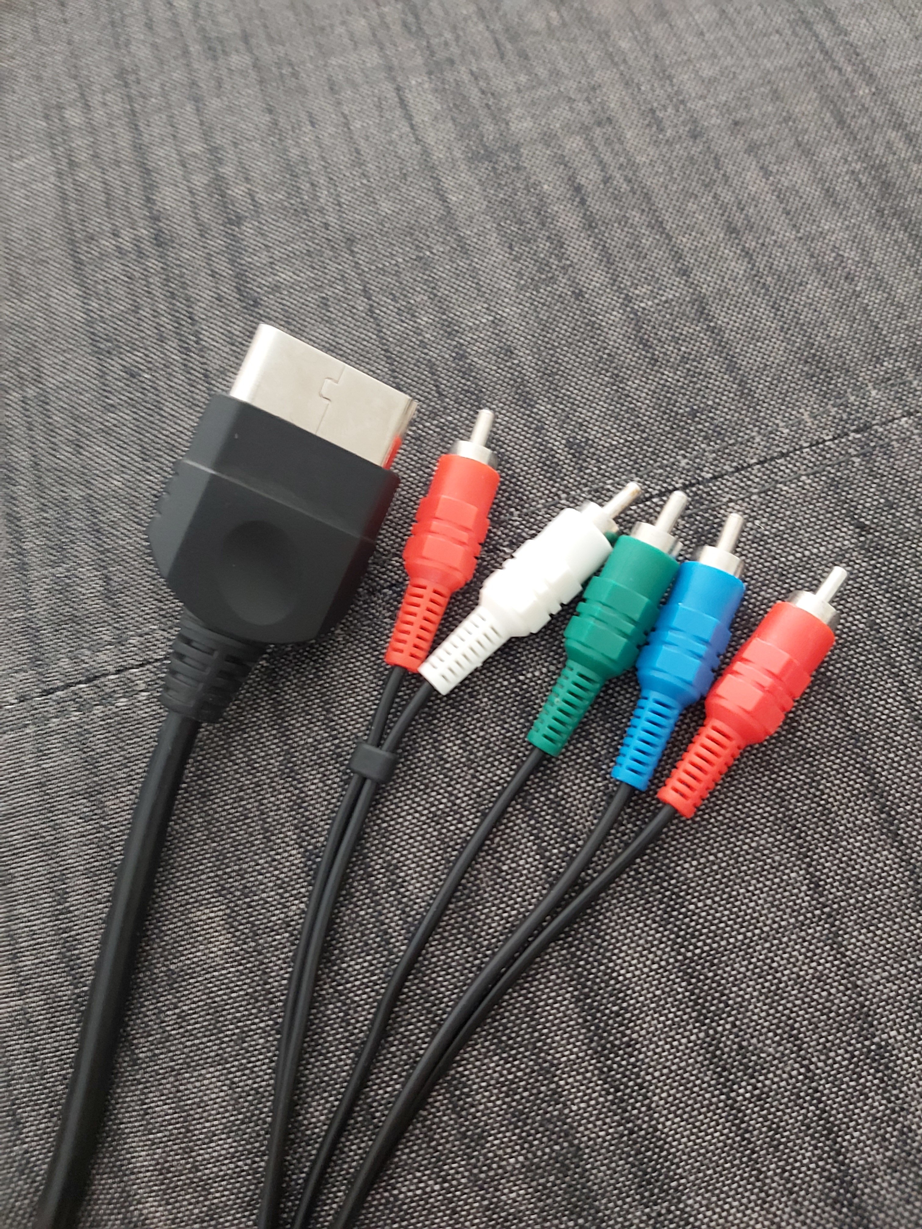
It came with a 120gb and component cable.

-
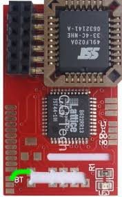
Is this a good find? I dont know to much about it, I have heard of executor chips but don't know the difference between the versions. I've seen some with lcds and usb ports. I picked it up at a garage sale for $40.
-
-
-
Is there anything I can do about that?
-
That would make sense because if I turn it right back on the time gets shorter before it shuts off again. It seem to get a bit warm in there too. I've tried putting a desk fan on it no change though. Would it be from the thermal paste under the heat sinks? One of then seems lose.
-
11 hours ago, KaosEngineer said:
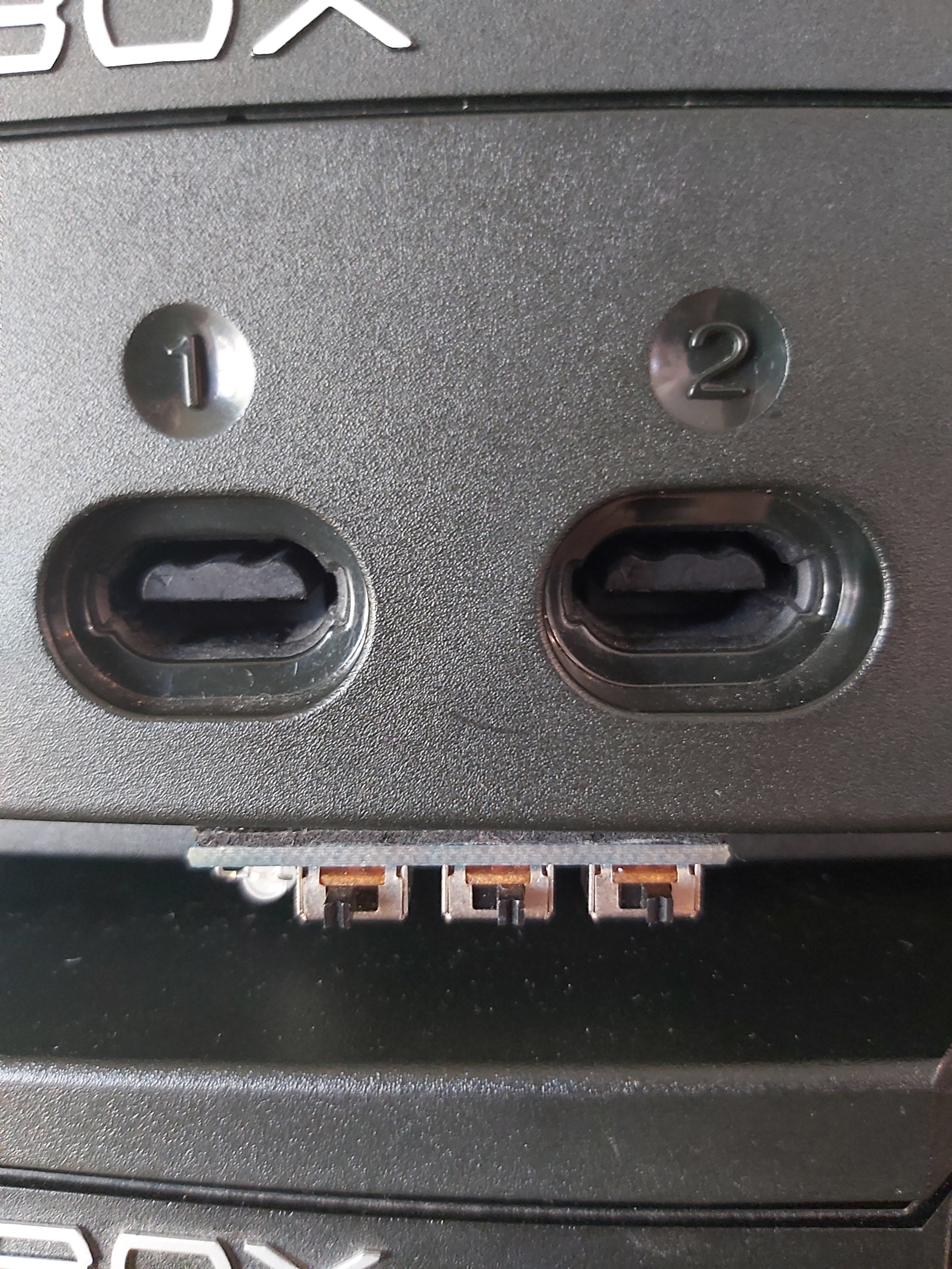
Trace rot - power signal trace damaged that leads from the front panel connector to the System Management Controller. Phantom power on / off can occur. The 4 thin traces are on the front edge on the bottom side of the motherboard.
Power/Eject Troubleshooting
I replaced the front panel board for one I knew worked and same results. I also looked at the motherboard and the traces look good. Over all this is one of the cleanest I've picked up inside and out. Anyone know what the shut down might be about? It does power on soon as the console is plugged in without pressing the power button and after a few minutes it shuts down. Please help.
-
That sucks
-
Awesome got it thank you guys very much!!! I've encounter a new issue though, after a few minutes the xbox is shutting down on it's own. Also does anyone use hexen? Is there a generic password to format the HD?
-
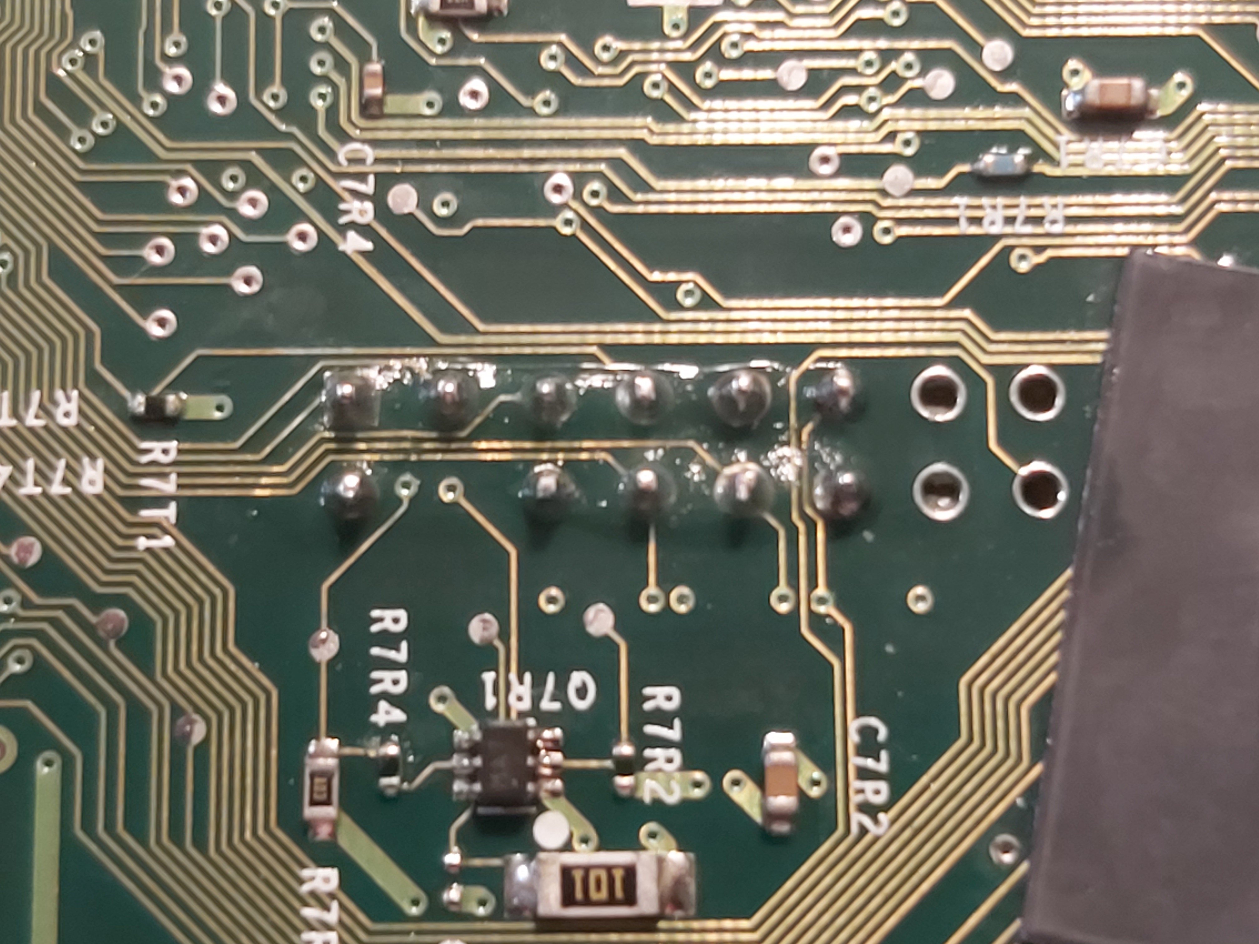
Any suggestions how too solder to that tiny point?
-
Where do I find the DO on the board
-
-
I feel like my issue is with the DO wire can someone please explain this? Also ill post some pictures tonight or tomorrow.
-
8 minutes ago, KaosEngineer said:
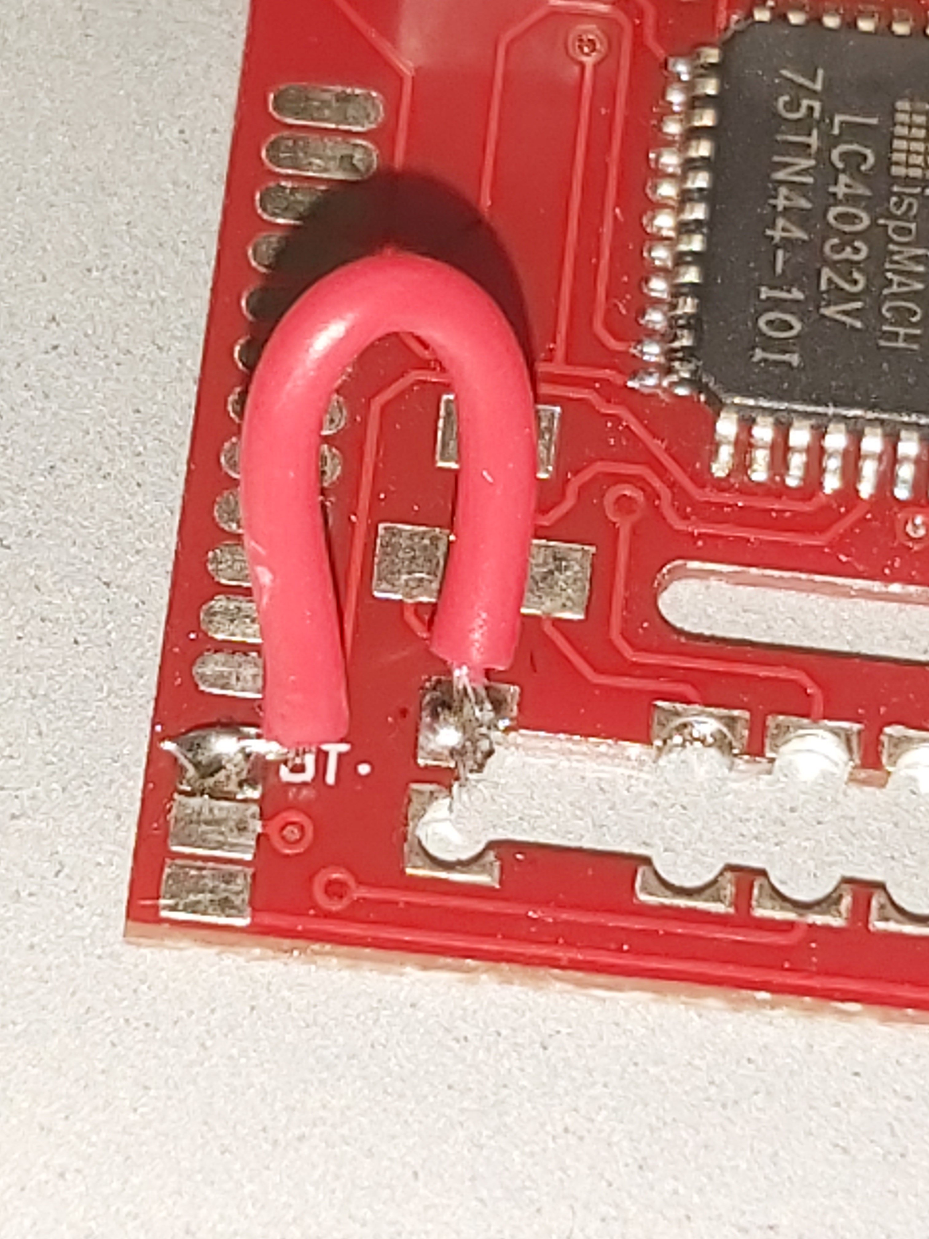
Did you connect the BT pad to the power signal resistor as most instructions show or connect BT to ground on the modchip for always on mode?
If BT to the power signal, you have to hold the power button for > 1 second for the modchip to be enabled. A short tap of the power button to turn on the console will boot the Xbox with the modchip disabled.
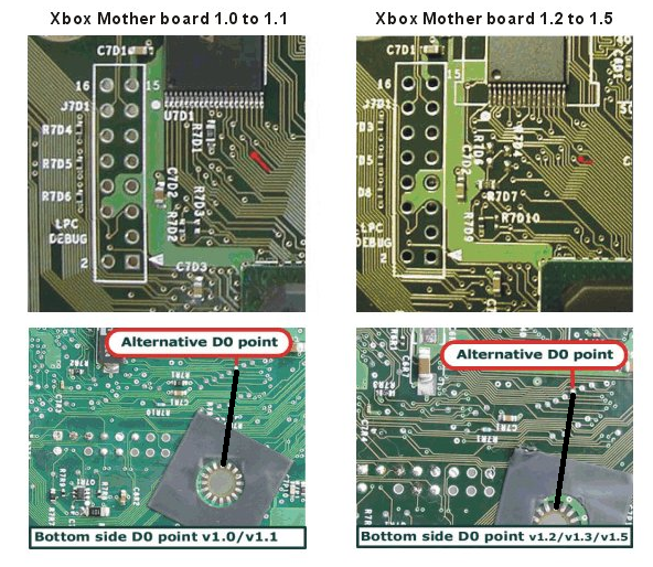
For always on mode, connect a wire between the two endpoint locations shown below:
Yes the BT is connected just like the picture.
-
43 minutes ago, SS_Dave said:
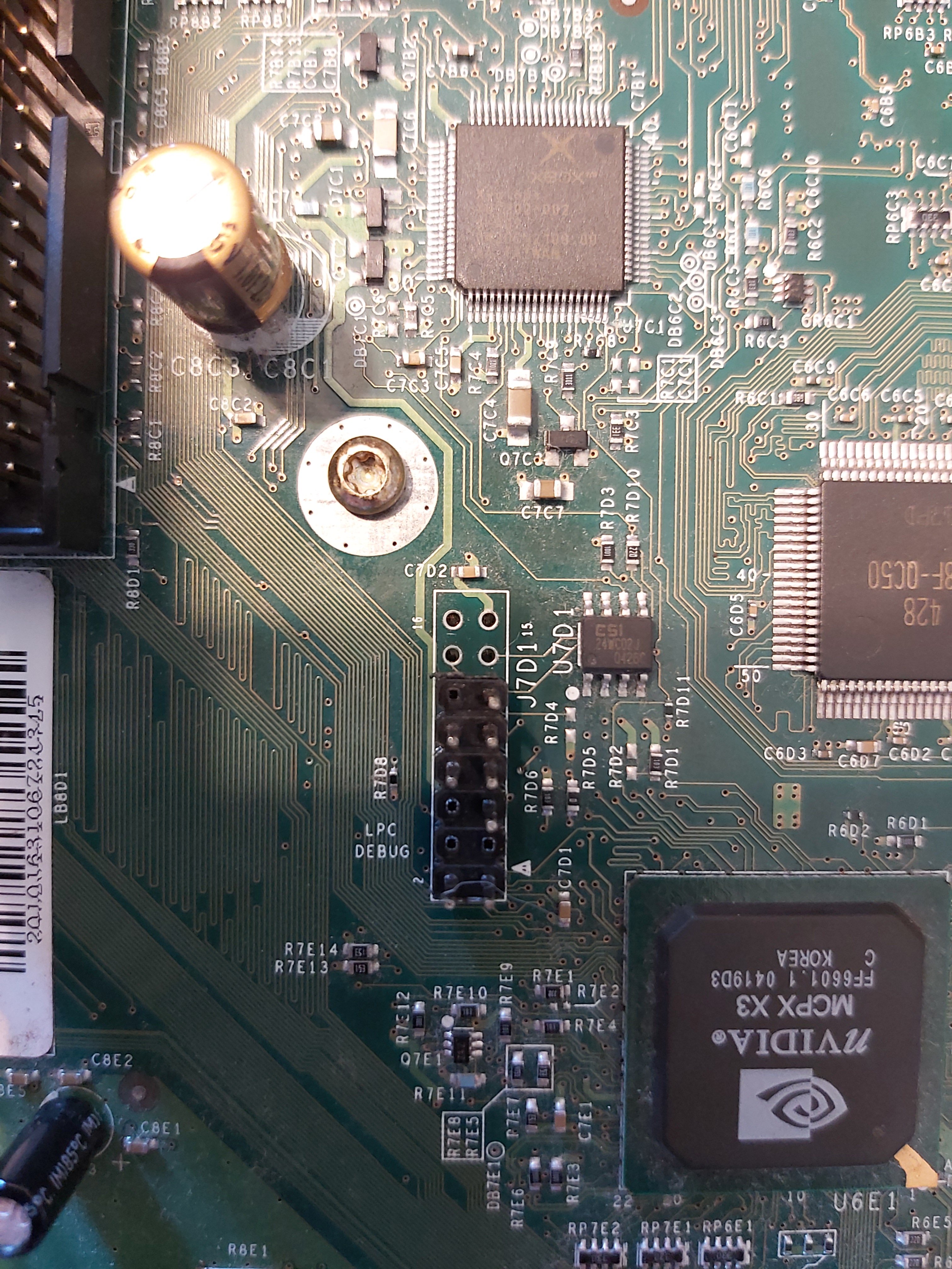
It would help if you posted some pics of the board and pin header install solder work.
If it appears to not booting from the modchip I would double check your soldering and the D0 location, Where is the D0 connected to (mod chip or ground)?
My preference is the alternative D0 point and just link to ground
With a Aladdin modchip I link ther BT to pin 2(Ground) as this forces the chi to be always active .
Cheers
SS Dave
Soft modding is like masturbating, It gets the job done but it's nothing like the real thing.Do I go from the DO on the chip to the ground on the motherboard? Or is there another DO?
-
I'm back with what I believe is v1.5 installed pin header and placed mod chip on it. When I start it up it starts up as if there is no chip. Seams like something keeping from booting from the chip. Any suggestions or advice?
-
I'm pretty sure this thing fraged some during the installation. Is it true that replacing the capacitors will fix this? If so can anyone send a like for the best place to purchase. It tries to load 3x then flashes red/green.
-
On 8/21/2020 at 10:23 AM, mattison1986 said:
I just put a new rebuild chip in and cut the trace. Still the same issue. I tried to run without the Aladdin xt chip and other scenarios all with the same results. It seem like it attempts to run 3x then starts flashing red and green.
-
-
Did I remove the correct pins?

-
I just put a new rebuild chip in and cut the trace. Still the same issue. I tried to run without the Aladdin xt chip and other scenarios all with the same results. It seem like it attempts to run 3x then starts flashing red and green.

.jpg.d3a2184339f8e7beb8d74fee3e89641a.jpg)
.jpg.baa09b0d09cda7ba0f5390427ac14218.jpg)
Board Life Status
Board startup date: April 23, 2017 12:45:48
Does This Look Familiar?
in Modchips
Posted
The disc drive worked thank you. Any suggestions on what bios to use with this chip set?