

trencherfield
-
Posts
490 -
Joined
-
Last visited
-
Days Won
33
Posts posted by trencherfield
-
-
Excellent. Well on your way now. Enjoy.
-
-
On 2/18/2025 at 1:49 PM, OGXbox Admin said:
I used a chameleon mod chip... but it shouldn't matter.
To give a bit of background, we know that Xbox motherboards were assembled and the TSOP was programmed while in system. That's why the LPC is exposed in the first place. They would boot from lpc and then program the tsop from it. So that's how we knew it was possible.
There was some talk about what effect D0 has on the MCPX and why it changes the address the Xbox boots from. It was then discovered that if the TSOP is blank the Xbox will boot from LPC. So MS didn't need to hold D0 low to boot from lpc.
So that gave us some hope that if we time it right, we can boot from LPC and flash the TSOP.I knew that if I left the chip on the LPC, even if lifting D0 I would never be confident that I actually flashed the TSOP. I just soldered D0 to the chip's D0 point. (Any ground on the chip will work) Then when I lifted the chip from the lpc pins I knew D0 wasn't grounded and the chip wouldn't be detected/flashed. I tried several different timings. Lifting off too soon would result in FRAG. Lifting too late and the XDK hardware refresh disk just wouldn't flash anything. I timed it just right and it flashed the TSOP(as well as rewrote the hdd. You should probably put an empty one you don't care to overwrite in there for this process.) The only risk on this is putting the chip down on the wrong pins. Make sure you do that right every time and you really can't hurt anything.
A small PCB between the LPC pins of the xbox and modchip with a multipole switch would be a nifty small-ish project that would be of great use here.
It could then be further developed to switch using a timer circuit to the perfect interrupt every time. -
6 minutes ago, ForceLikeObi said:
So when I do this I get a service required error 12. It starts the boot animation for the original retail kernel then just errors out.
There are some fixes that might help depending whats wrong with it and which model it is. This is the downside of the retail kernal with DVD check etc and your hard drive has to be locked as well.
-
That's probably the DVD drive being faulty.
-
Go into your Openxenium settings, go to add/remove bios, add bios, select retail/onboard bios, thats it.
You can then upon booting into openxenium goto select bios, then retail. -
51 minutes ago, Chungaloid said:
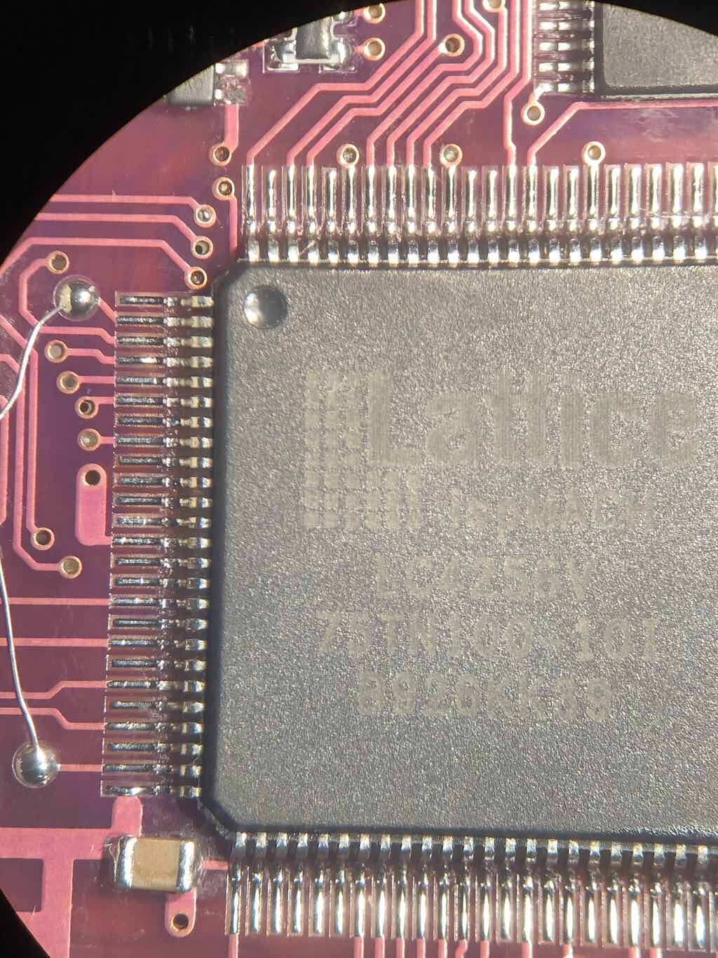
Okay, removing the switch did it and now I'm able to identify the CPLD as an LC4128V(B). Once the new one comes in I'll get it on and (hopefully) programmed. Thanks a ton for your knowledge!
No problem.
")
-
 1
1
-
-
8 minutes ago, Chungaloid said:
Okay wonderful, I appreciate the pics and explanation!
Edit: I'm assuming the flash enable connection has to be bridged once CPLD programming is complete, correct?It's not flash enable, it's flash protect. So no, if you remove the switch and have cut the trace to use the holes, you do not need to re-connect the trace.
It's not required no. It was only there to stop anyone (kids) flashing the chip in the past.
-
 1
1
-
-
-

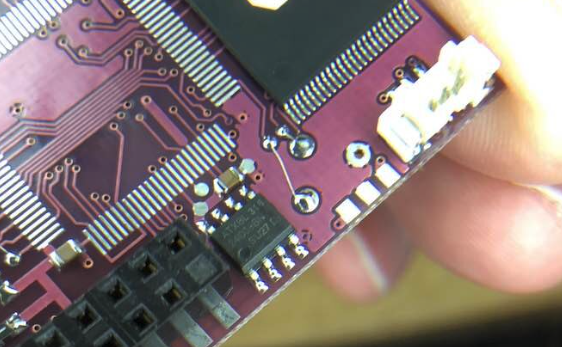
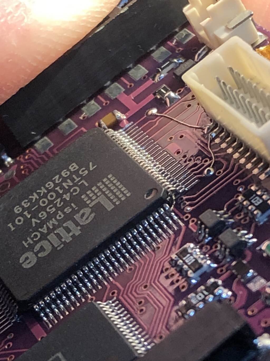
The trace is cut at 1'o'clock on the larger pad. This is the bios protect line from the switch. This is after removing the switch.
This then allows the use of the switch pads to the backside of the PCB.
Otherwise you would just solder the TMS & TDO pads to the LCD connector directly. The above was done to keep the wires out of the way for later CPLD removal and preliminary testing.-
1
-
-
On 2/10/2025 at 1:15 AM, Chungaloid said:
Absolutely uncanny timing lol. I recently acquired a for-parts X3 purple and quite literally (about 30 minutes ago) just installed ispLEVER because my programmer came in yesterday. Instead of posting my long winded explanation of symptoms in a new post, I'll follow this and let you know how it goes. Thanks!
Edit: @trencherfieldI have a couple questions to make sure I'm doing this correctly, as my programmer is not able to detect the suspected bad CPLD. I kind of figured that this may be pretty common for blown CPLDs, but I want to make sure I'm using this correctly.
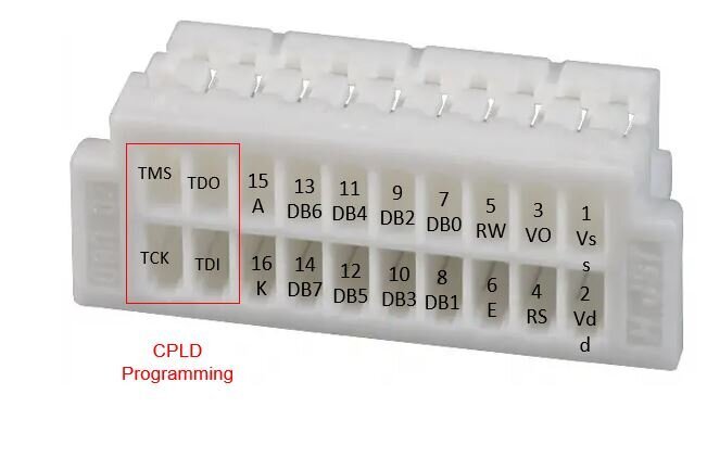
First question I have is verifying the labeling of JTAG points on the LCD connector. Based off the picture of what I believe is the LCD male connector that plugs into the board, is this picture I labeled accurate?
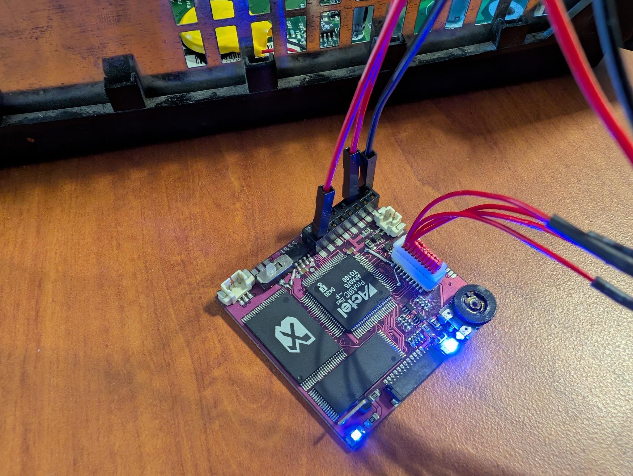
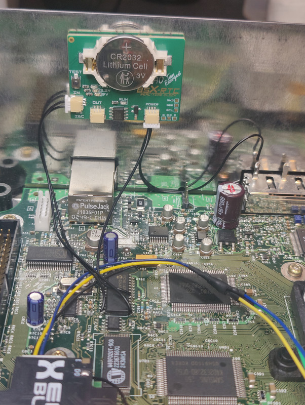
Secondly, I have one of those knock-off aliexpress Lattice HW-USBN-2A programmers. After perusing the documentation for it, I'm under the impression that it does not supply power to the board, and instead the VCC is an input and is supposed to be powered either from an external power supply, or from the PCB you're working on. Essentially I have the 4 JTAG points connected to the programmer via the LCD connector, and then I have 3.3v and ground from the Xbox's LPC powering both the X3 and the programmer from splitters that I made from jumpers. I also have the X3 powered with a 5v jumper from the LPC as well. I'll add some pics of this just to be sure.
All of this is just to see if you see anything glaringly wrong with my setup and unrecognizable CPLD's are a thing. All LCD connector posts have continuity with their respective CPLD leg. Additionally, the 3.3v LED (I think? Of course, now I'm drawing a blank, but it's the LED closest to the 1.6 power post) is flickering a lot when connected to power source. I've searched for that issue, but I haven't found anything anywhere about it.
Thanks!Hi,
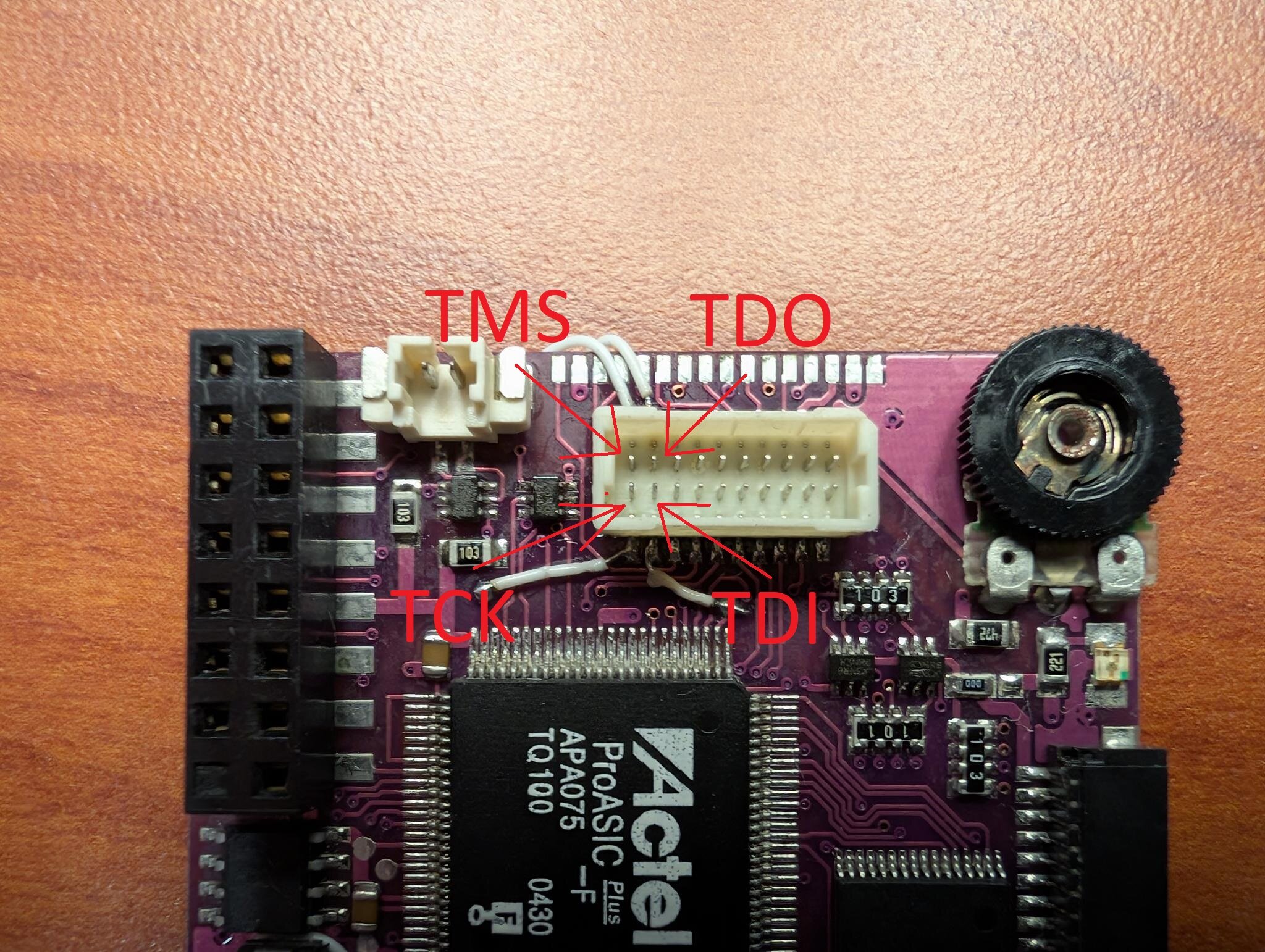
Yes, it appears you have connected TMS and TDO to the switch points with the switch still in place. This is shorting one or the other to GND probably. I removed the switch.
I also cut the trace from the switch hole before soldering TDO to it.
Since you are using insulated wire and still have the switch in place, then you should just connect your TMS and TDO wires to those pads only on the PCB. Not to the switch points.
-
1
-
-
Check that trace.
-
4 minutes ago, mwalkuski said:
Ya sorry, I specifically meant the 1.2 and 1.3 boards. I couldn't find any examples online where they were populated so I'm guessing they removed them after 1.1.
They look like that because I touched them with the iron just to reflow to solder in case there were any issues from the solder splash.
Ahh right thought it didn't look factory.
Just been looking again comparing boards. Checked your 3 blue resistors.
Can only suggest as you intend. Remove the LPC connector entirely, clean and re-do when you have the solder and flux. Touch up the blue resistors with the flux.
You'll notice a huge difference when you use it and leaded solder. -
52 minutes ago, mwalkuski said:
Thank you both for your responses, however I would like to respectfully partially disagree with your assessment.
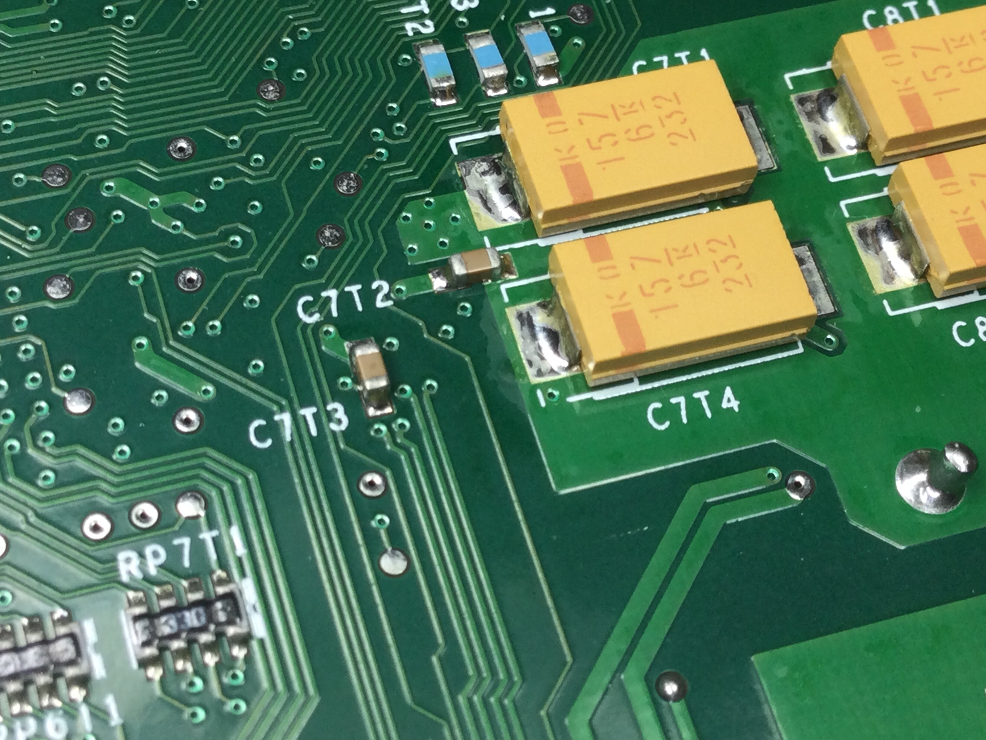
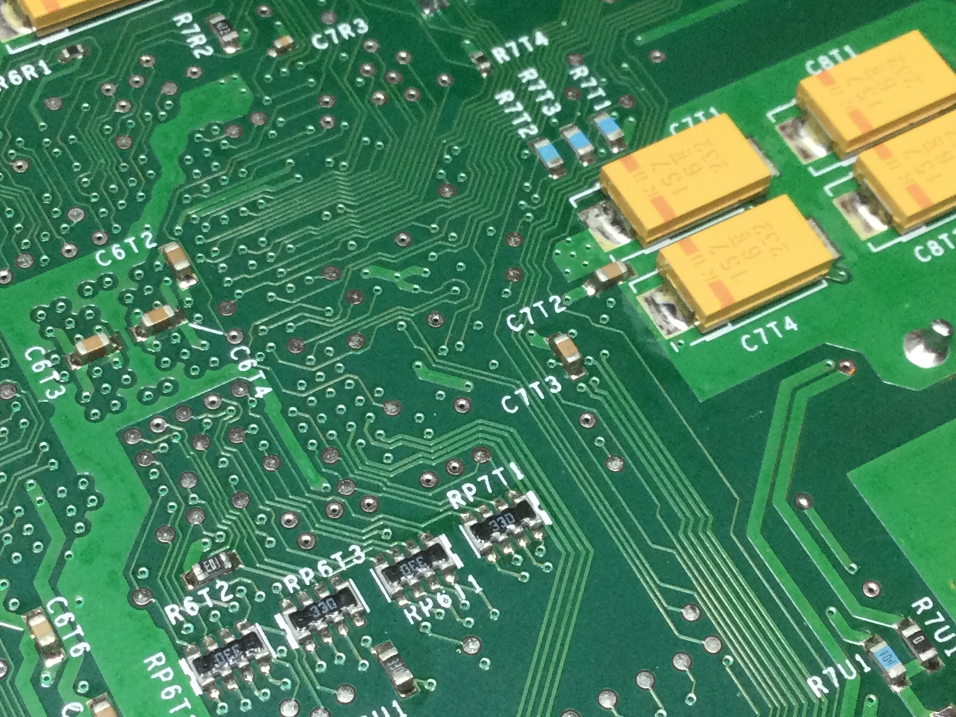
C7T2 and C7T3 are not supposed to be populated with anything on these boards. Neither of my boards have those filled in, and I was not able to find any others online that had those populated. Additionally, I was sure to take the utmost care while handling the board, so I do not think any pieces are missing.
This is my V1.1 which is the closest I have to hand to your V1.2
It's not a common board V1.2.
Next closest to hand I have is V1.4 which is built up at the moment, but as you say your other board is the same then that must be the case after the 1.2 revision. The picture of yours oddly shows what resembles a square smd imprint in the solder too which must just be the photo. But they are there on V1.1 as you can see.-
1
-
-
C7T2 and C7T3 appear to have been in place and now missing in action.
The above capacitor replacement soldering has not been flowed into and through the board sufficiently enough with good flux.
These are multi layer boards. There are connections within the holes vias to these layers. Some may be dry jointed.
This soldering and the above, isn't sufficient quality unfortunately. I would advise that this board will now need remedial work and carefully going over properly.
Given the missing caps and other unknowns, it's far too difficult for us to remedy this board for you herein.
Not trying to snipe you or anything such, we all started somewhere, but some more practice soldering with suitable flux may be a better aim.
Board handling is paramount too to avoid damages.Maybe buy some RMA218 flux and try reflowing those joints for practice (the cpu caps are a known heat sapper to the ground plane) and re-do the LPC. If you can find replacement smd caps for those missing ones you can practice those as well.
Then maybe pickup a scruffy working Xbox motherboard and fit a new pinheader to that.
Best of luck anyway.-
1
-
-
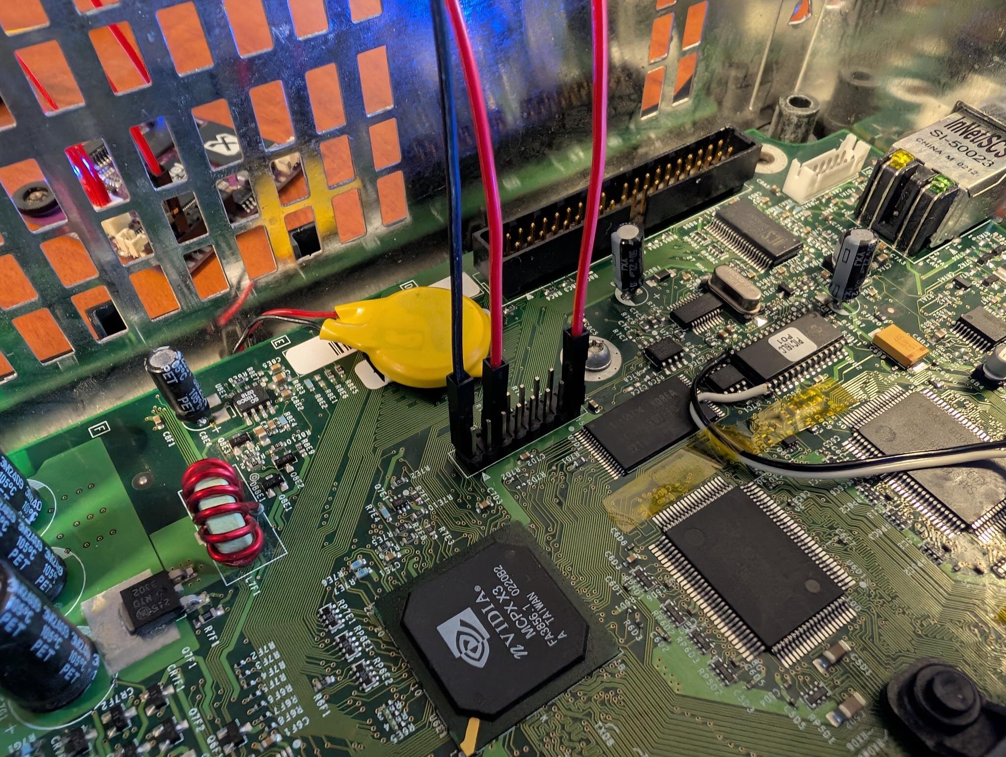
These points need observation on and by the LPC port (reverse side) for possible bridges.
-
-
-
With an Xbox of this age (v1.1) and the problem you have of the power button not working, this would indicate that the clock capacitor has likely been leaking and has damaged the traces at the front of the board. Usually the underneath ones.
You would be better served by purchasing say, a £20+ openxenium chip and hardmodding the console, removing the leaky clock capacitor asap and give the other CPU caps a good visual as they may need changing too.
I would attend to the above before proceeding with any softmod with the Xbox in this state.
Need to open it up and get the hardware in order first. Plenty of guides regarding the clock capacitor and the power/eject corroded traces restoration methods.-
2
-
-
1 minute ago, Bowlsnapper said:
I've heard that Kekule has maybe had some life things pull him away. but I wish I saw more of him around. He's a very talented guy and has done some cool things. I'm glad you're sorta able to finish what he started and actually bring it to people. It isn't easy to get these going and the BOM is pretty obscure, with sourcing being problematic, at best.
True enough indeed. It's a challenge and somewhat frustrating sometimes, but it's sommet to do at the end of the day and enjoyable when it works. I'm actually more glad that it works on the original chips so people can fix them at last.
-
Cheers bud.
Wouldn't be possible without Kekule's and others work. Nod to them lot.
Hope it helps folks out at the end of the day, that's what it's all about.-
3
-
-
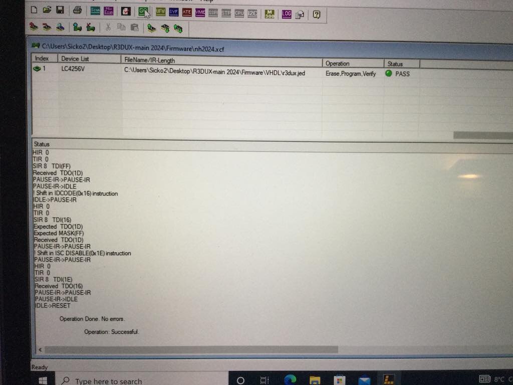
Here's the .jed !
Xecuter 3 jed
Good luck.
-
4
-
2
-
-
PART 5
Now either you've done as I did and connected your JTAG points to the LCD connector or left them until now. Consult the PDF or redux github for which pad is what. They are easily identified and mirror each other on the chips.
You can solder your 4 JTAG wires (any that fit) to the pads if you didn't do PART 1.
We program the CPLD. Everything should come up trumps if we are lucky.
Great.
Disconnect your JTAG & remove your soldered JTAG wires if you went that way. Now lets test it.
Success!
-
1
-
1
-
-
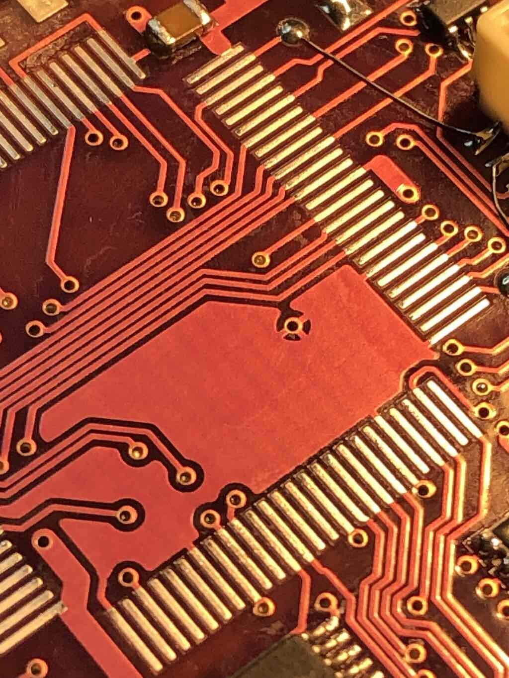
PART 4
Now we need to clean up those traces carefull with the iron and your solder braid. Use the flux! Do not press hard.
Move the braid and iron in line with the pads to the inner area. Reposition the chip each time. Do not rush. Do not overheat the traces and the solder mask is very thin and fragile. Let the braid glide in nice strokes to soak it up.
Hopefully we end up like this.
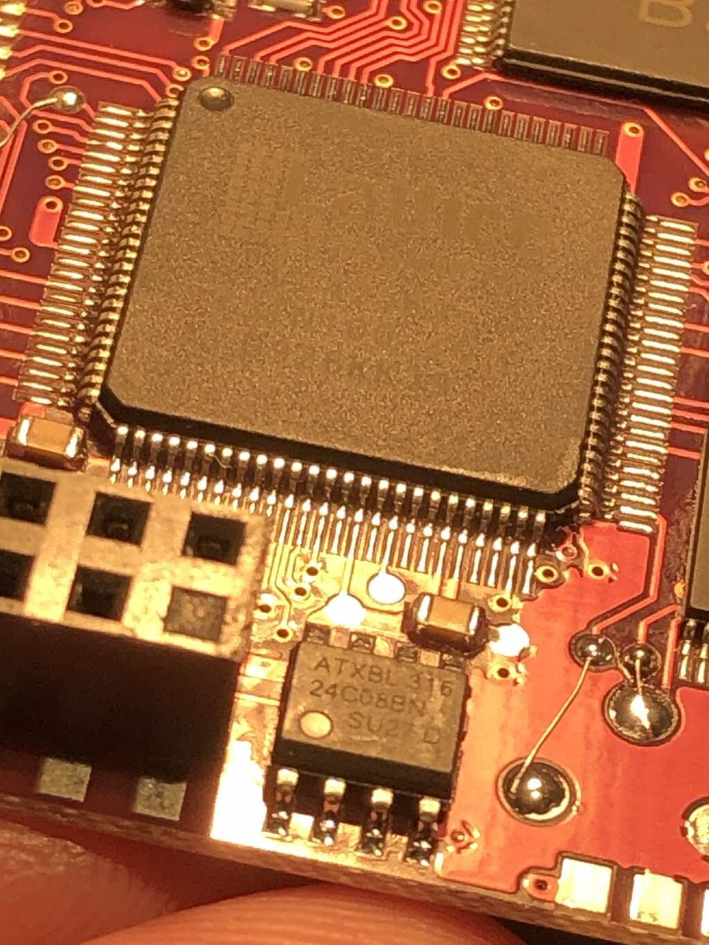
We want to start from a good position here.
Flux is king and good solder.
Flux the pads, postition the new CPLD onto the pads. Note the pads are narrow, actually thinner than the end of the chips pins. Get it perfect, it will save you later.
Solder the corners first. Watch your background with the iron body on connectors etc. Its awkward.
We want to end up looking like this.
onto the next part...
-
1
-
1
-


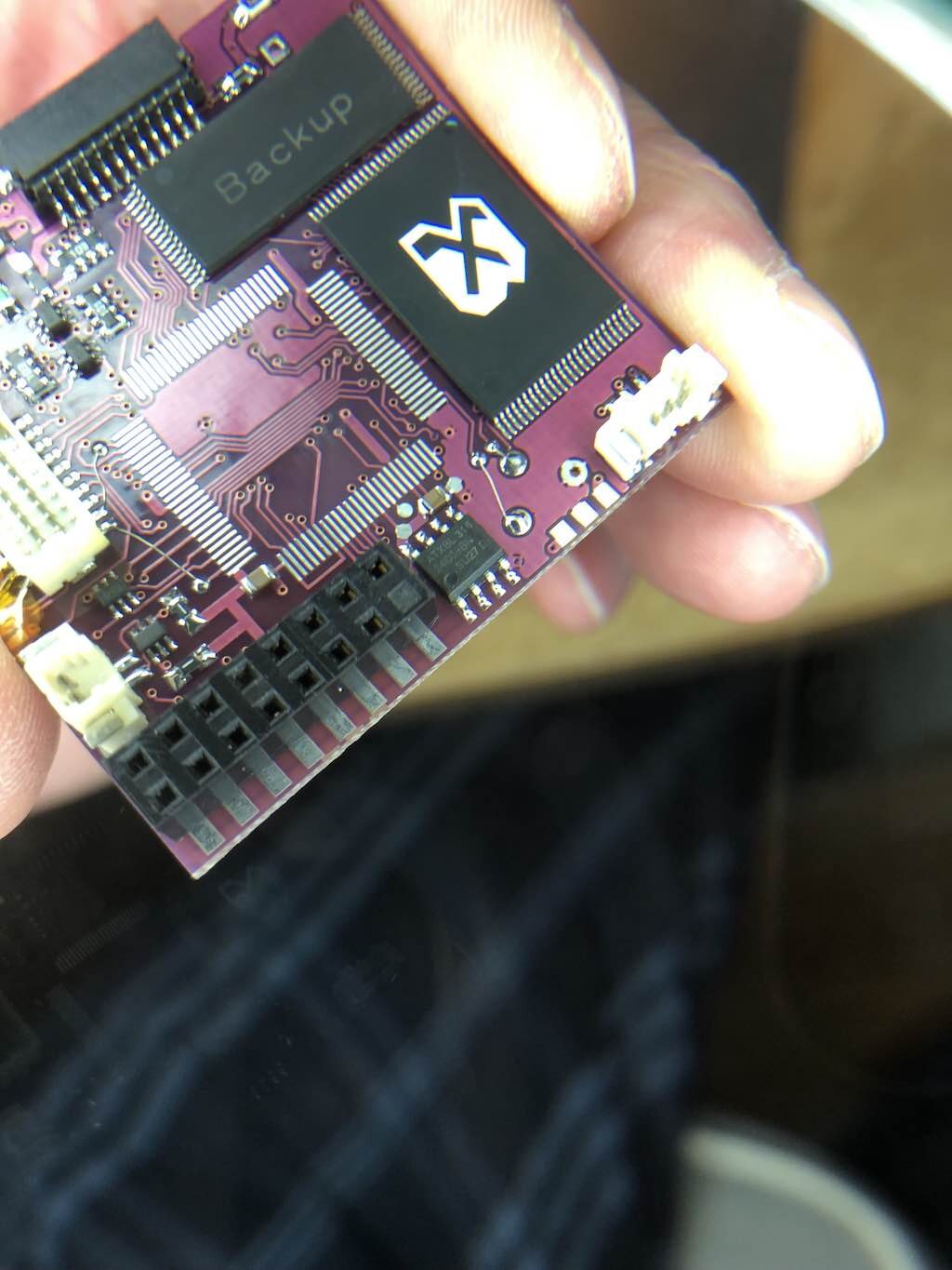
Board Life Status
Board startup date: April 23, 2017 12:45:48
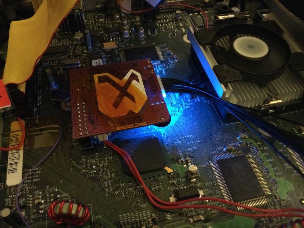
Tutorial - Lets repair a broken Team Xecuter 3/CE Modchip...
in Modchips
Posted · Edited by trencherfield
guide
You're welcome, glad it's worked out for you.
You need to read the associated user guide I made for R3dux Xecuter 3 from the original build thread.
I have added it here too for you.
R3DUX supplemental guide.rtf
Ignore about the D0/LAN/HD connector for genuine Xecuter 3 chips. This is only for R3dux pcb's. Your X3 is still the same.
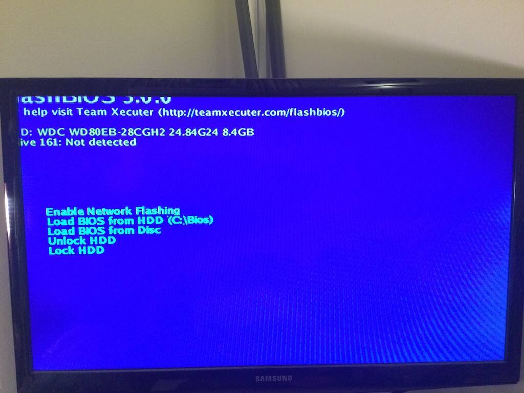
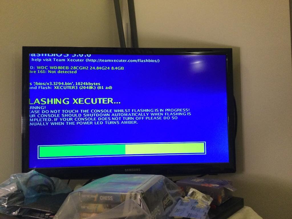
Also, you need to flash the 256k r3dux flashbios 3.1 to the backup chip, as this is required to boot the backup.
flashbios_31_r3dux_256kB.bin
... which is also available here
Flash files.