

Hispano
-
Posts
34 -
Joined
-
Last visited
Content Type
Profiles
Forums
Calendar
Store
Posts posted by Hispano
-
-
11 hours ago, SS_Dave said:
I still believe the modchip has a blank EEprom
Hi Dave! What do you think about my 2 latest posts?
And thanks for all your help! I will keep your updated when i will receive the replacement modchip!

-
Another thing that i tried now and makes me think that we are right and the chip is blank is that i tried to boot with it connected and with D0 to chip to too but without the SST chip and my Xbox FRAG. Then i supose that is a failure from EEPROM, the chip cant read from it because is blank
Then all my installation is fine!
Im right, Dave?

-
14 minutes ago, SS_Dave said:
I still believe the modchip has a blank EEprom.
That list you found lists "Usually due to a failed or improperly installed modchip"
We have been over your installation and besides some soldering issues at first, The soldering issue has been fixed so that leaves the Mod-chip at fault.
If it was a installation problem then just disconnecting the D0 wire ( Red wire) from the modchip would not allow the Xbox to boot normally.
Cheers
SS Dave
Soft modding is like masturbating, It gets the job done but it's nothing like the real thing.
What do you think about this too?
4 hours ago, Hispano said:Hi again Dave! I was doing the last continuity and resistance test against bottom board points and always got 0 Ohm with it but i have a question because i have doubts if im doing it well: what measure should i use 200, 2k, 20k, 200k or 2M Ohm?
And another question, in continuity mode (beeper) all beep fine (long beep) but in pin 2, i always got beep with interruptions, is normal (i reflowed this pin a bit more but i dont get a long beep) get interrupted beeps?
And i discovered too that the 2 ground pins (2 and 12) beep fine (long beep) against every ground hole (screw hole) and one against another
What do you think about my new questions? I want to exhaust my chances to fix my chip installation

Also modzville (the chip seller) told me that he always tested them before send them but maybe is a problem of the aladdin itself and not the SST chip
And thanks for help me a lot with my installation and to choose a better solder
I want receive my Hakko to try it! 
-
7 hours ago, SS_Dave said:
I am very confident that a new mod-chip will fix it as with all your testing if I was the seller I would be sending you a replacement chip and including a return postage so I could see what happened to the 1st mod-chip.
Cheers
SS Dave
Soft modding is like masturbating, It gets the job done but it's nothing like the real thing.
Also i discovered a table with different lights of Xbox and i was wrong calling FRAG to my problem, mine is Christmas lights
 .
.
I hope that mistake dont make differences to get a solution
-
7 hours ago, SS_Dave said:
I am very confident that a new mod-chip will fix it as with all your testing if I was the seller I would be sending you a replacement chip and including a return postage so I could see what happened to the 1st mod-chip.
Hi again Dave! I was doing the last continuity and resistance test against bottom board points and always got 0 Ohm with it but i have a question because i have doubts if im doing it well: what measure should i use 200, 2k, 20k, 200k or 2M Ohm?
And another question, in continuity mode (beeper) all beep fine (long beep) but in pin 2, i always got beep with interruptions, is normal (i reflowed this pin a bit more but i dont get a long beep) get interrupted beeps?
And i discovered too that the 2 ground pins (2 and 12) beep fine (long beep) against every ground hole (screw hole) and one against another
What do you think about my new questions? I want to exhaust my chances to fix my chip installation
-
11 hours ago, MadMartigan said:
Where are you located? I probably have an extra one you can have for free, if you cover shipping. Not sure how much that would be though.
Im from Spain
")
-
11 hours ago, SS_Dave said:
The Hakko brand (FX-888D) is probably the best of the budget brands, I have a 15+ year old Hakko and it's never been a problem. I have got a 2nd hand piece with a large tip for soldering parts like the capacitors next to the heat sink and the smaller hand piece with a fine tip for soldering IC's and the like.
Thanks Dave! i ordered one and a few tips more to do better solderings! I hope that with the replacement of my Aladdin Xblast my Xbox will run fine, i keep you informed
Also, if i got always continuity and the same voltages (after and before resolder LPC points) all my work should be correct, right?
-
2 minutes ago, SS_Dave said:
It's not really the tool that makes a good job it's the operator, But a good tools help make the job easier
I need practice more
But what do you think about my last work soldering in pins? You see all fine?
And i will look for a hakko then! Thanks for your tip Dave!
-
1 minute ago, SS_Dave said:
That's a 100% improvement, And that a good result for you with the seller sending you a replacement.
Then my solder looks good now?
I did it with a cheap solder with temp regulation (i used a JBC without regulation before)... I think i need buy a new solder, weller is a good brand?
-
19 minutes ago, SS_Dave said:
I suggest you send a link to this page as I believe you have thoroughly tested your install, Even thought the solder work is not the best I have seen I have seen a hell of lot worse ( and I mean solder that looks like the person used a stick welder) that's working.
Yes, I linked him to this thread. I rebuild all my solder pins and reflow the pins in Aladdin Xblast but my Xbox continues FRAG with chip connected and D0 too but booting without D0 connected. He will send me a replacement.
What do you think about my solder now?
Thanks for your help Dave!
T
-
13 hours ago, SS_Dave said:
It is sounding more like the 49lf080 is empty. When I made my Xblast chip, You program the CPLD ( Lattice chip ) 1st then you can either flash the 49lf080 in a external read/writer or boot the Xbox with a working mod-chip chip then hot swap to the new Xblast chip and flash the 49lf080 from a Xbox app. It's possible the seller mistakably shipped it with a blank eeprom (49lf080).
Hi again Dave! I have a doubt... Could be the pin 16 that it makes FRAG my console with the chip connected and D0 connected to it? I ask because i didnt be able to remove the solder from this pin hole in LPC port

Im waiting too for a answer from modzville, he said to me to send the pictures of my solder and tell him my tests in his discord channel, i posted all and im waiting for his answer
-
2 minutes ago, SS_Dave said:
Lets see what the seller replies to your email.
Thanks Dave! I will wait for a answer to my email and i will keep you informed about it.
-
 1
1
-
-
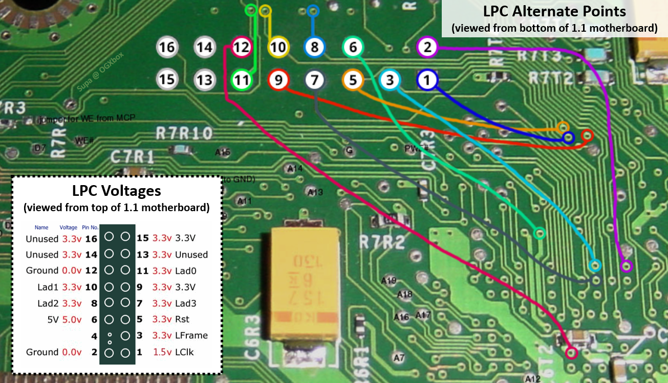
On 2/20/2023 at 6:04 AM, SS_Dave said:
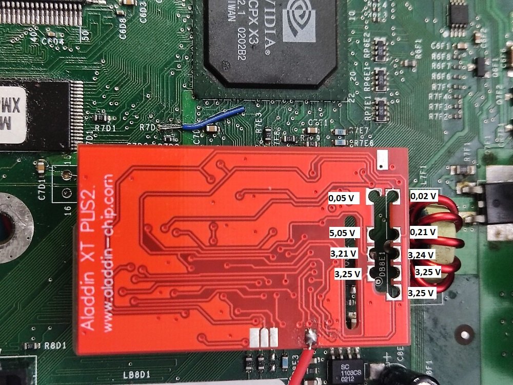
Check the voltages while the chip is connected to the main board and powered up as per this pic
Dave, i also have did a quick test more without D0 on chip connected but with chip connected to measure voltages in chip without FRAG, i got all right except pin 2 (ground), i got 0,02 V instead 0V in thi pin. In the rest of pins all voltages are right
Then the chip could be empty without any bios flashed?
-
1 minute ago, MadMartigan said:
It was ModsvilleUSA. He stands by his name and will surely make it right, if the chip is indeed the issue. OP should out to him and see if maybe he can offer some trouble shooting tips.
29 minutes ago, SS_Dave said:As you have paid for a working Xblast mod chip I suggest you contact the seller and ask politely for a replacement as most sellers are happy to help.
I sent a email to him, i will tell you if i could get a solution to get work my Aladdin Xbast
-
10 minutes ago, SS_Dave said:
The last resistance readings you did lead me to think you have a faulty mod-chip, I think the CPLD is probably working as it activates the D0 but when it comes time to read the 1st 256kb of the eeprom for Xblast OS this is where is fails. I wonder if the seller forgot to flash the eeprom.
Another question, i always got wrong voltages with chip connected but got all voltages right with it disconnected... Could be a bad flashed chip the reason? I dont understand this
-
4 minutes ago, SS_Dave said:
The only real way to 100% confirm the chip is at fault is to either plug a different chip on your Xbox or fit your Xblast chip to a known working chipped Xbox.
But seems that it should boot into latest bank to flash (xblast bank flashed) as i read in this post: https://mmmonkey.co.uk/og-xbox-xblast-aladdin-install/
Its strange... What should be my next step?
-
1 minute ago, SS_Dave said:
The only real way to 100% confirm the chip is at fault is to either plug a different chip on your Xbox or fit your Xblast chip to a known working chipped Xbox.
Then i need to buy another (one from Aliexpress) and swap it (if the new chip works) and flash my xblast?
-
12 hours ago, SS_Dave said:
You set your meter on Ohm's and test from the solder on the bottom of the board to the point's on the mod-chip where I got you to test for voltage.
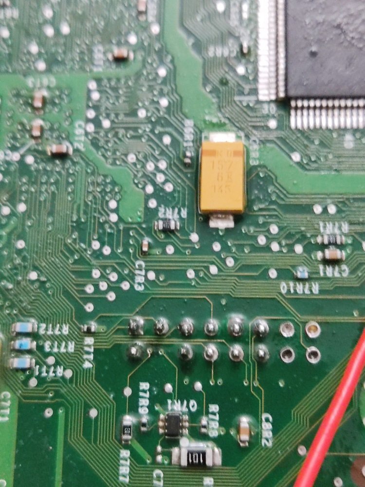
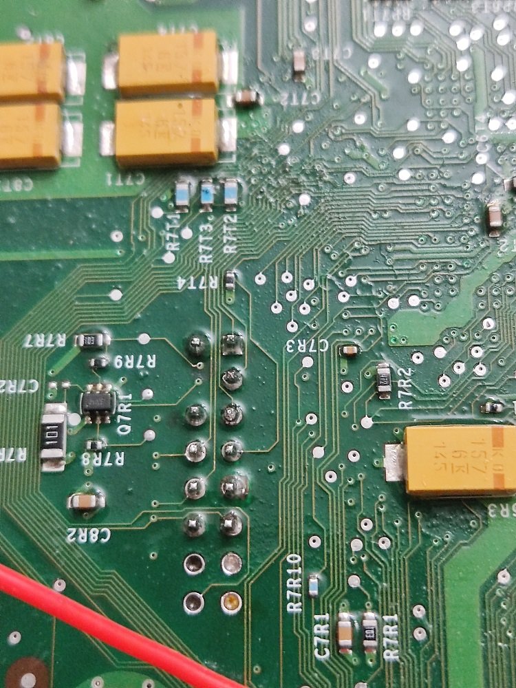
I put vertically the board and tested from soldered pins in the bottom against the points in the modchip and in Ohm's scale in my multimeter and in all pins from modchip (1,2,5,6,7,8,9,10 and 11) i got 0 Ohms.
Also i tested in points from bottom of the board and got 0 Ohms too like in this image:
I tested too with beeper position in my multimeter doing both test from above (pins in mainboard vs points in chip and (pins in mainboard vs points in mainboard) and always beeped.
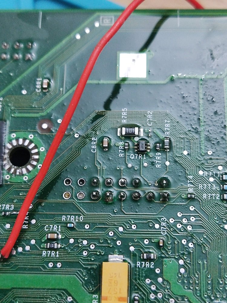
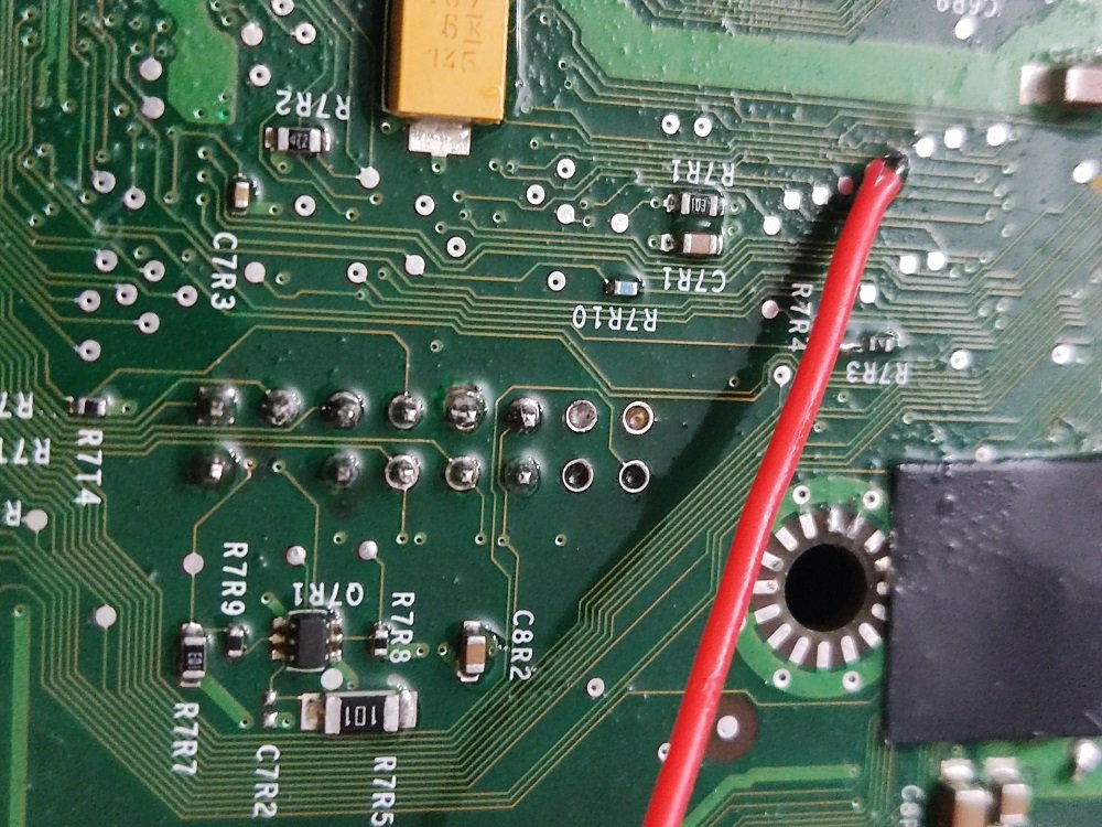
12 hours ago, SS_Dave said:What happens if you remove the red wire from the mod chip and solder it to ground ( Screw hole ) instead of the mod-chip
If i solder the wire from D0 in mainboard to a screw hole (ground) always happen the same thing like when is connected to D0 in chip, always FRAG
Also i tested the continuity from both D0 points (board and chip) and i got 0 Ohm too
Any idea to solve it?
Thank you very much for your patience trying to help me!
-
2
-
-
1 hour ago, Prehistoricman said:
Can you check continuity to ground vs pin 1 with the modchip connected?
I checked voltage from ground (pin 2) against pin 1 with modchip connected (horizontally) and got 0,02 V and testing continuity (omega letter from multimeter) i got 0,02 too instead 1 or 0... Im out of ideas
-
1 hour ago, Prehistoricman said:
Yeah I misread your table from the start of the thread. 0V when connected is not good because LCLK should be running at all times. Can you check continuity to ground vs pin 1 with the modchip connected?
With my board vertically? Or from fast solder 1 and 2 pins in horizontal position? I tested them with the board disconnected against their points that barnito's told in his guide. Im totally lost now and im afraid of damage my xbox

-
41 minutes ago, SS_Dave said:
Can you do a resistance test between the mod chip pin 1 ( the point that's reading 0.02volt) and pin 1 on the MB (the pin that was reading 1.7 volt)
You will need access to both sides of the board.
And if you can test all the other pins as well
I dont know how to do it
i checked continuity with bottom board pins against bottom pins like the schematic from barnito's, doing it only pin 2 give me 1 in omh scale instead 0
On 2/17/2023 at 10:37 AM, Hispano said:With respect to continuity everything is correct except pin 2
-
10 minutes ago, Prehistoricman said:
Your LCLK and LRESET seem dead.
In your previous results, LCLK on pin 1 was 1.7V which looks good. This indicates that there is a disconnect between the Aladdin and the LPC header. Check continuity from pin 1 to that corner hole that read 0.02V
Dead in motherboard?
i got 1.7V on pin 1 measuring the voltage without my chip connected but when i connected it i always got +-0V
13 minutes ago, Prehistoricman said:Also check continuity of LRESET (pin 5) to the hole that reads 0.21V.
How can i check continuity with the modchip connected? I checked it with my motherboard disconnected against the points in the bottom from barnito's guide
-
13 hours ago, SS_Dave said:
Check the voltages while the chip is connected to the main board and powered up as per this pic
Hi Dave! Do you have any idea what might be wrong? All voltages seems right except 3 points in the chip. Here are my voltages:
-
4 hours ago, SS_Dave said:
Check the voltages while the chip is connected to the main board and powered up as per this pic
Thanks Dave, should i check voltages with D0 connected to chip?
5 hours ago, SoftMachine said:If I'm wrong, someone correct me, but I think the Xbox is supposed to FRAG with a chip installed and D0 not grounded, so that would mean either your soldering is no good (and I've seen worse work before) or the chip is no good. Maybe if you have another chipped Xbox, you could test it in that, or if you own another modchip you could throw that in and see if it works.
I always can boot right from TSOP with the chip connected but without D0 connected, i cant boot from chip to XblasOS to select bios banks (2) or TSOP.I can always boot directly from TSOP with the chip connected but without D0 connected, what I can't do is boot from the chip to XblasOS to select the BIOS banks (2) or TSOP with D0 connected to the chip.


 T
T

Board Life Status
Board startup date: April 23, 2017 12:45:48
Help! Aladdin Xblast FRAG but Xbox works with it disconnected (Green light)
in Repair
Posted
Hi Dave and all the mates that helped me to solve my problem! Finally the problem was the chip and my solder job is fine all you said!
With my modchip replacement all is working like a charm!
Thanks to all of you for your patience and help to solve it!