

booyabeetz
-
Posts
25 -
Joined
-
Last visited
Content Type
Profiles
Forums
Calendar
Store
Posts posted by booyabeetz
-
-
3 hours ago, Dtomcat18 said:
Rev 2 is done and works! So much easier than my Frankenstein approach


Looks great! I will probably build this jig as well if you ever get around to publishing the gerber file on your repo.
-
1 hour ago, Dtomcat18 said:
@booyabeetz new board ordered with update for different clamshell
")
Awesome! I meant to suggest adding the component information to the silk screen but it looks like you were thinking the same. Good stuff!
-
19 hours ago, Shadow07 said:
Sweet thanks to both of you. Can't wait to build one of these things.
I forgot to mention that I also started out building the regular/original ogx360 before I tried to make the 2-channel internal. The original is easier to make and so it's a better starting point if you do not have a lot of experience soldering etc.
The 2CH/4CH internal variants also have components that are intended to be mounted using a hot air station or hot plate (such as the oscilator crystals and micro-usb connectors) whereas the regular ogx360 can be done entirely with a soldering iron. Just a heads up:
-
57 minutes ago, Shadow07 said:
Do you have a BOM?
This is kind of why I actually started with the 2-channel variant for this. The repo has the BOM with Digikey quick links etc. In any case most of the components overlap with the 4-channel variant so I guess you could infer the 4CH BOM that way:
https://github.com/bolwire/OGX360I-2CH/tree/master/Hardware/OGX360I-2CH Main
Personally I will probably wait for updates from Dtomcat18 before I order anything for the 4CH.
-
14 hours ago, Dtomcat18 said:
Updated my Github with more information (getting there)... This update is the pinout for each connector (other than controller port connector... already out there).
https://github.com/dtomcat/OGX360I-4CH/blob/master/Wiring/Pin Signals.md
Nice! This clarifies a lot.
-
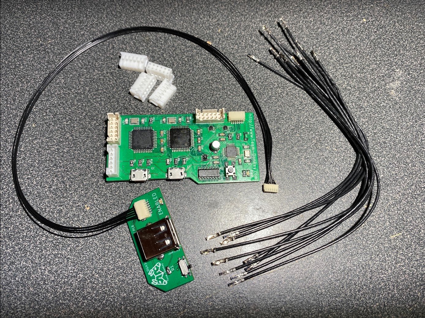
So the 2CH appears to be working great after I reversed the position for the LED on the mini board. I also mistakenly had the 12 pin JST cables reversed (from controller ports to ogx and ogx to xbox). Apparently wired controllers will still function as expected in bypass mode even with these cables reversed, however the wireless controllers will not work. In any case this means I can move on to the next project. The 4CH is on my todo list. I have the PCBs ready but I likely need to stock up on more components. I definitely cooked one or two ATMEGA32U4's from when I tried to burn the boot loader's with my bad breadboard setup...
-
1 hour ago, Dtomcat18 said:
I have added my first findings for the ogx360i-4ch onto my GitHub. It’s not much yet… but is critical for making your own kit!
there will be more to follow
Excellent! Great Work! In the meantime I had a look at the schematic for the 2CH and realized that I probably soldered the LED on the mini-board in the wrong orientation. Having flipped it around now gives the me the expected green light when the enable switch is flipped. Apparently I don't have enough experience to figure out which way a diode needs to point unless its explicitly spelled out on the pcb itself lol. I'll reconnect this back into the console in the morning to see if everything will work. Per the schematic it also appears that the extra 6 pin JST cable port is intended "to be used for future expansion board". I am not that good at reading schematics but I think it might be a method to daisy chain two of the 2CH units.
-
1 hour ago, Dtomcat18 said:
I’ll try to look at the schematic sometime soon. Working on my next project. I’ll try to see what I can see.
Thank you for the reminder. I just realized that I can view the schematic file in the repo. Maybe I will be able to figure it out.
-
I think I figured out how to make the JST jumper cable. It was not anything special like I had previously imagined. Right now with the 2CH hooked up to the console I am able to get it working in bypass (i.e. flipping the micro switch to allow wired controllers to communicate to the console). In this mode the wired controllers (as connected directly to the console) work as expected. Beyond that however I am not getting much luck in getting the wireless mode to work. I am testing with a known working 360 wireless receiver however the green "enabled" LED on the mini board with the microswitch does not turn on regardless of what I do. The wireless controllers are pairing properly to the wireless receiver however manipulating the buttons on the controller has no affect on the console (this is with the microswitch set to either position).
To troubleshoot further I flashed Ryzee's debug firmware to the master Atmega32u4 and all the tests passed. This also confirms that the 2CH board can see and communicate properly with the wireless receiver.
So at this point I am stuck and unsure of what to do...
EDIT: I also have a 6 pin JST cable port on the 2CH that is not connected to anything. I have not yet figured out what this is for.
-
25 minutes ago, Dtomcat18 said:
I’ve never seen this before. Where are the details? Git?
-
Here is the latest I have for the 2CH. I am somewhat stuck at this point because I am not quite sure how these cables need to be made/wired up.

-
32 minutes ago, Dtomcat18 said:
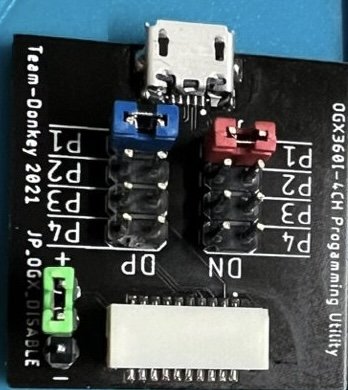
Awesome. Great to hear! There is a programming board that you select which chip you want to program
Ah that makes sense. I also heard that some people install the 2CHi & 4CHi with relays. Is that what you are doing as well?
-
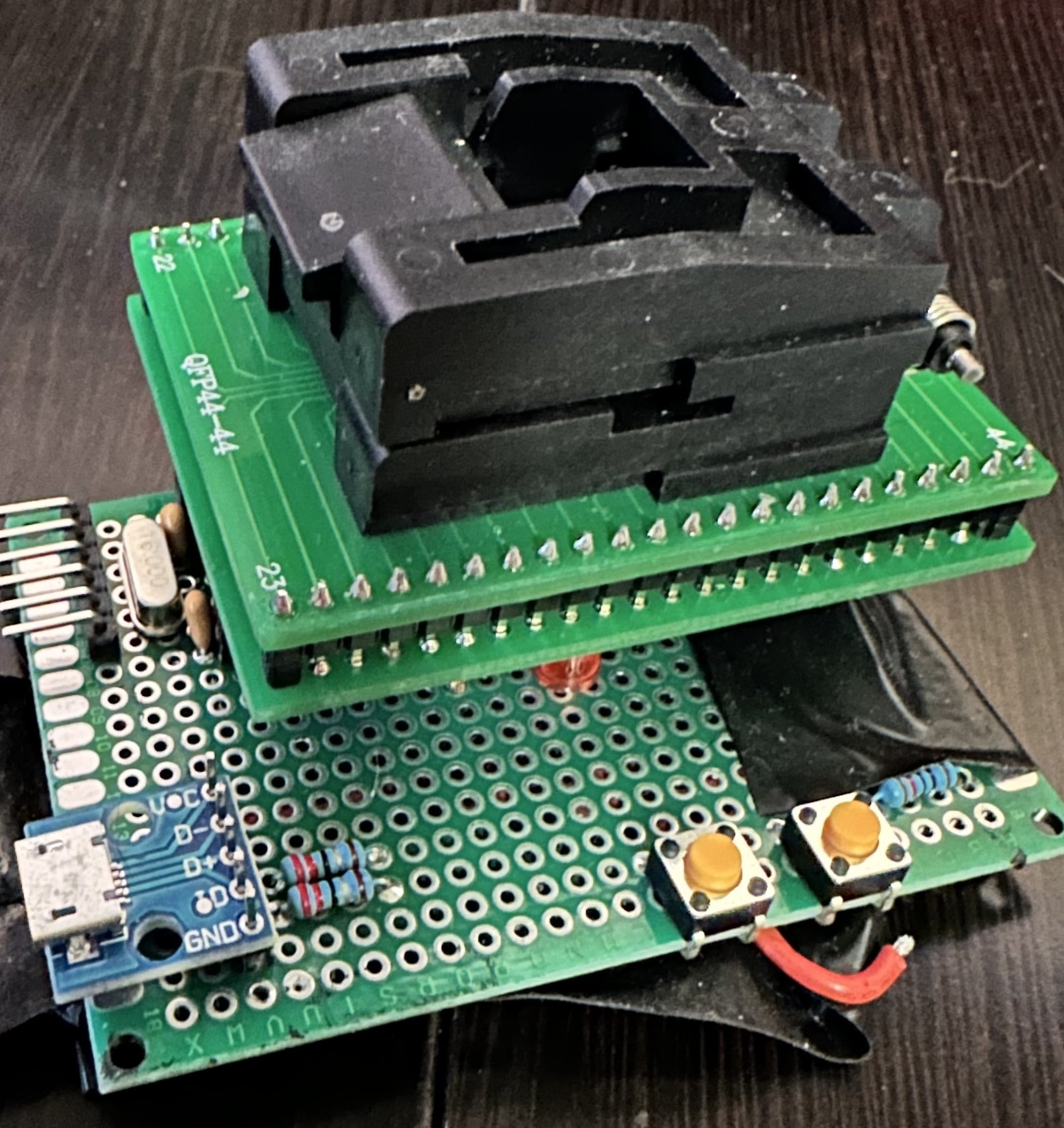
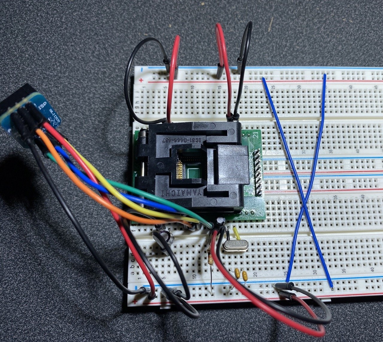
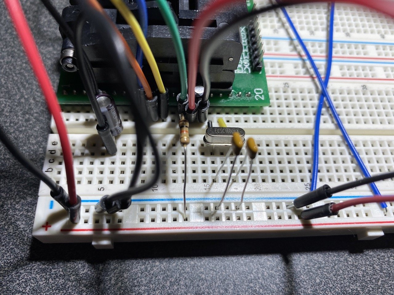
I took another crack at setting up the clamshell socket for burning the bootloader and thankfully this time it works. Like suspected my wiring was way off because I relied on the pin markings on the clamshell for how I should land my wires. Next step for me will be to start soldering the smd components for the 2CH.
In the meantime it dawned on me that I don't understand how the 4CH gets the ogx firmware uploaded to each chip. The 2CH has the 2 micro usb ports so I imagine the process is similar to how the regular ogx360 gets programmed. The 4CH however has no micro usb ports from what I can tell. In that case how does each chip get the ogx programming?
-
44 minutes ago, Dtomcat18 said:
the OGX360i's are DONE!!!! (most likely never again!). going to take a break and will try to get all the documentation up on my git next week. A lot of blood, sweat, and tears went into this! But, I got lots of information out of it and after I post, many more should be able to make these a lot easier than with the current information posted online. I'll post an update when it's online.
fantastic. I will probably make another attempt this week with the test socket I have. I have a zip lock bag full of parts ready to go for a ogx360i-2CH. I am sure your findings will help a lot when I start putting that together.
-
3 hours ago, Dtomcat18 said:
Spacing inside to too large and pins on chip too short so one side can make contact… other side falls through

pins spacing is just over 12 mm (barely) and tip to tip pin spacing on atmega is 12mmx12mm.
That's weird. This is the one I bought and the pins appear to align properly: https://www.ebay.com/itm/383556932163
I looked for the test socket based on the package type for the ATMEGA32U4 which appears to be 44TQFP...
-
I don't understand. The clamshell adapter is too large? In what way?
-
4 hours ago, Dtomcat18 said:
Success! All the boards are working
What a relief. Just have to get the rest of the harnesses complete and ship them to the buyer!
I did find one wiring issue (had a 50/50 chance of getting it right... and of course I didn't). After making that change, everything is working! After I get these out the door, I'll fork the Github and update it with my findings. I'll make a BOM, wire harness guidelines/schematic, etc. Once it's up, I'll post here... probably at least a month out.
That's great news. The wiring harness stuff is another area that I am completely unfamiliar with. Getting some additional documentation on this would be a huge deal.
-
1 hour ago, Dtomcat18 said:
Did you ever check the pins. Looks like same adapter I used and I bet the pins are off
Thank you for the reminder. I just beeped out a handful right now with a multimeter and its exactly like you suggested. The numbering for the pins on the chip and the numbering for the pins on the adapter are completely different. What a mess. Now I see why you designed your PCB to mate with the clamshell directly.
-
23 hours ago, Dtomcat18 said:
Finally made a programming cable... and I'm able to run the flash and run the test firmware (passes) and then flash the main firmware back.... Working Great. Now to build the main Harness and do a final test. ::fingers crossed::
Awesome! Keep us posted.
-
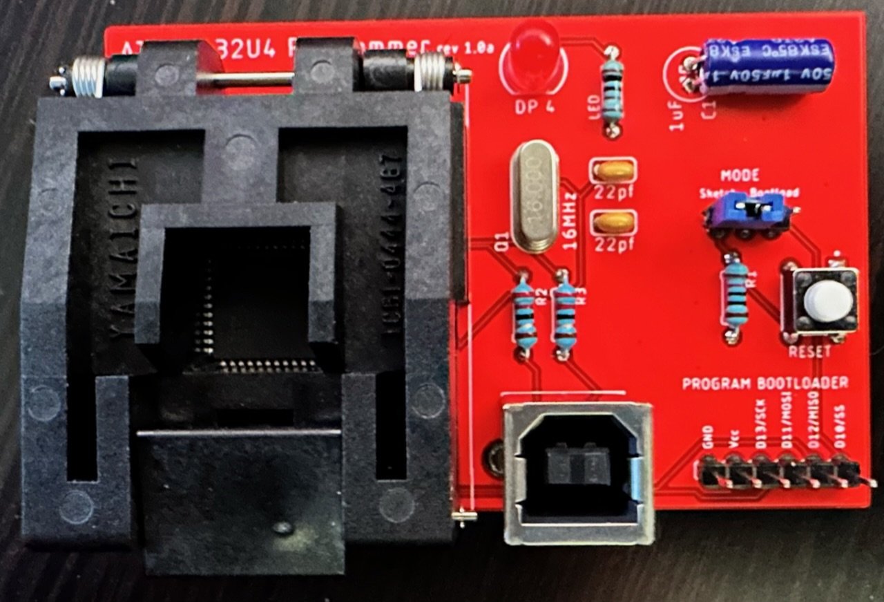
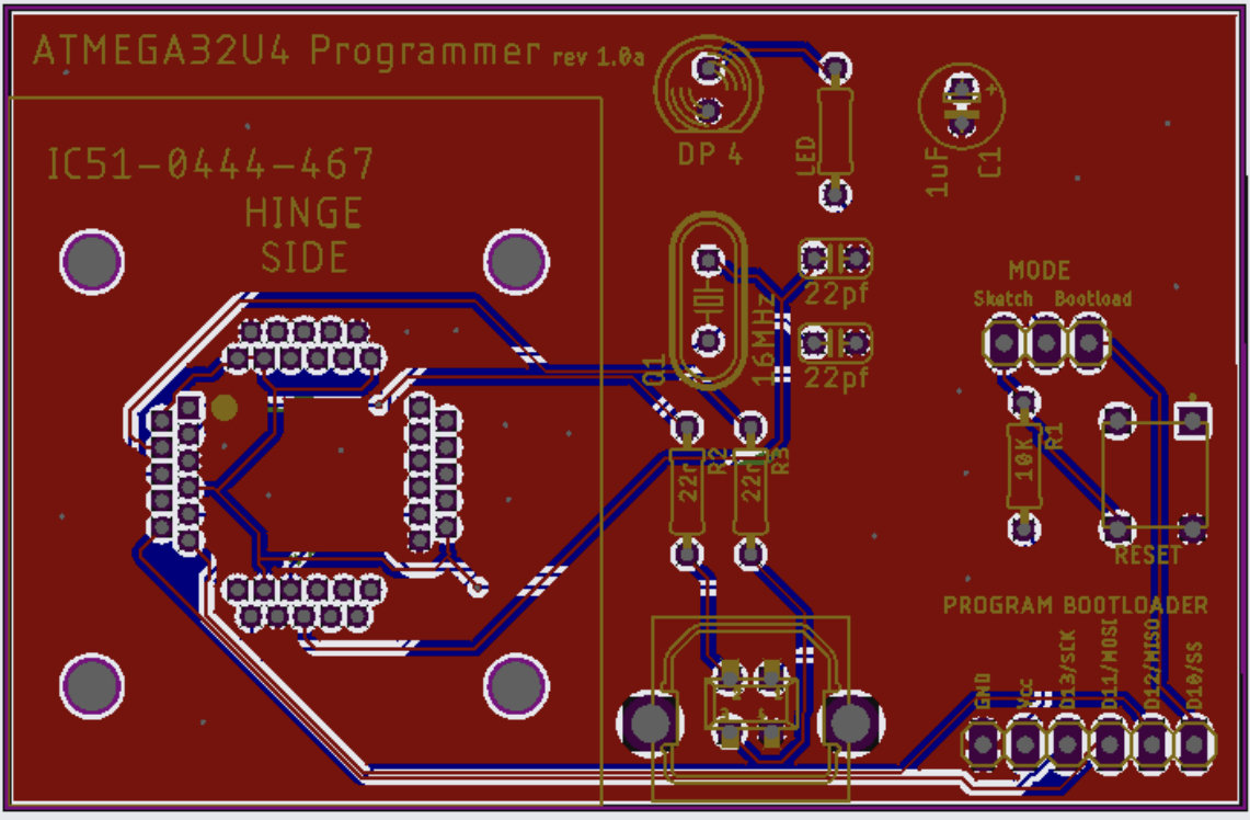
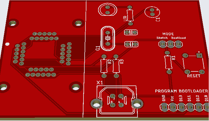
12 hours ago, Dtomcat18 said:
Here is what I made to make a little more professional look
Just ordered a set of boards... now just wait the month it takes to come from China
Thats so cool! I really need to start tinkering with KiCad one day. Do you have a github repo going for this?
-
On 9/18/2022 at 3:37 AM, Dtomcat18 said:
Just thought of something. A lot of these clamshell adapters have messed up pin numbering. So chip pin one is like pin 5 or 6 on my adapter. Did you account for this? That may be your issue
Yikes, I never considered that as a possibility. I guess I will have to check everything with a multimeter. Thank you for the heads up.
-
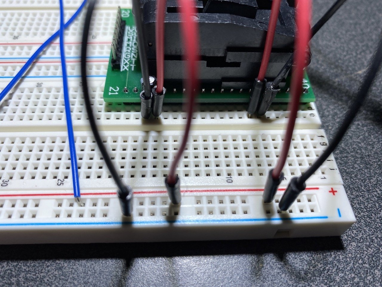
Yup. Thats exactly what I need to see. Maybe I am not that far off. Here is what my rig looks like right now. I have changed it several times trying to get it to work:
-
 1
1
-
-
11 hours ago, Dtomcat18 said:
I used the first link you posted. Created a socket design I’ll post a picture later… watching football
That would be great. I must have wired something wrong since I made one or two chips let the smoke out already

-
Some documentation would be great. The details on making the internal 2CH/4CH are pretty slim. I started the process of making the 2CH however I hit a snag with burning the boot loaders onto the Atmega32u4's.
I am curious how you are burning the boot loaders in your setup. My understanding is that you could transplant the 32u4's from existing Arduino's or you can use a clamshell adapter/ breadboard setup to program individual 32u4's on their own.
I am using these two pages as a reference:
https://murchlabs.com/monday-experiment-bootloading-an-atmega32u4-with-arduino/
https://electronut.in/bootloader-atmega32u4/
The main difference with my setup is that I am using the clamshell adapter instead of a breakout board. Here is a video of similar situation for a 328p:
Board Life Status
Board startup date: April 23, 2017 12:45:48
OGX360i-4CH :)
in Hardware Mods
Posted
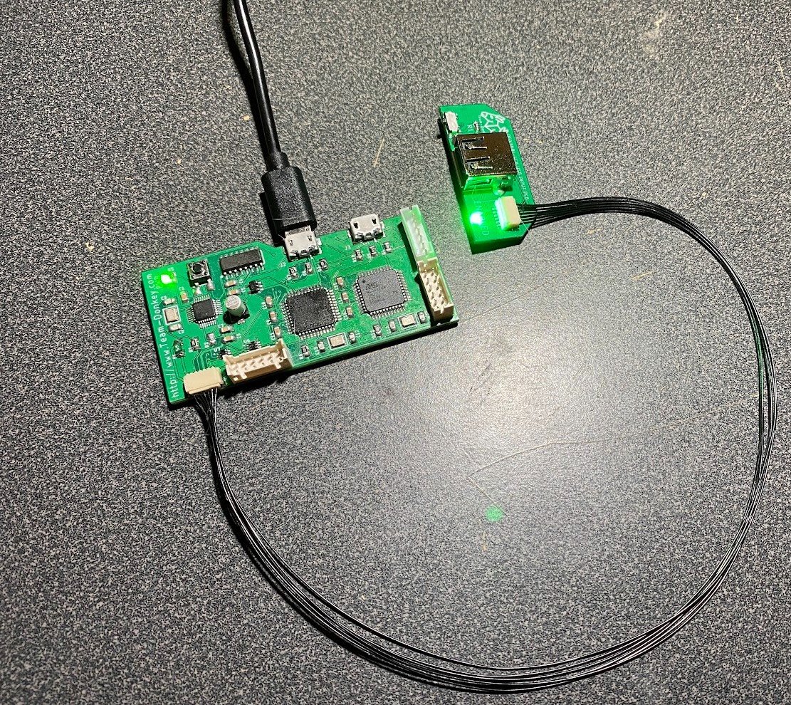
Thanks again for making the gerbers for this board available. I finally went ahead and placed an order for some pcbs so I can have one of these nice programming setups for my collection. This will also let me free up my breadboards for other projects.
Once complete I think I will start looking into making a 4CHi for my collection as well.